DirectRoute Product Overview
Overview
DirectRoute (DR) is a licensed, on-prem, automated fleet routing optimization tool with intuitive design, powerful mapping insight, and drag-and-drop functionality. DirectRoute easily interfaces with most existing accounting or ERP software, and can be used as a standalone application or with add-on modules and integrations for:
-
Single or multi-day Routes
-
One-way deliveries or backhaul pickups
-
Multi-depot planning
-
Street-level, turn-by-turn directions
-
Customizable reporting
-
Financial analysis of Routes and fleet operations
To learn how to use DirectRoute, see the DirectRoute User Guide
Installation
System requirements vary based on the software module licensed for use, the number of users, and type of operating system. Click below for details.
Local Machine Installation
The DirectRoute install files, and subsequent update files, are generally downloaded by licensed users from the Trimble ClientCenter. This user must have administrative rights on the machine to perform the DirectRoute installation.
For installation instructions, see the DirectRoute Installation Guide.
-
Each licensed customer (primary contact) receives an email with specific instructions on how to access the download, install the application, and find the product code/license number.
-
The installation cannot be done remotely.
-
Licensing and access to purchased Appian software add-ons/ modules are included in the installation download.
-
Request an alternative method for installation if the user system or network prevents the download or installation process.
-
This may include a mailed copy of the installation (certified, registered mail), or an onsite installation by an assigned Appian Implementation and Training Consultant.
-
-
Updates usually occur a few times a year. When updates are released, customers are notified via email with change details and instructions for installing the update. Each release update also includes an updated Help file.
-
Assistance during the download and/or installation is available:
Trimble email support — [email protected]
Phone - (800) 663-0626
The download file includes the DirectRoute program and component files, including:
-
.NET 4.5
-
Crystal reports
-
PC*Miler embedded Map/Mileage System
-
Address Cleanup file
-
Zip9 Data file
-
Help file
-
ResourcePro Module* (if purchased)
-
SchedulePro Module* (if purchased)
-
TerritoryPro Module* (if purchased)
-
Transportation Modeler Module* (if purchased)
System Requirements
System requirements vary based on the software module licensed for use, the number of users, and type of operating system.
Use the table below to determine requirements.
| Minimum Requirements | Recommended | |
|---|---|---|
OS |
Windows 11 / Windows Server 2022 |
Windows 11 / Windows Server 2022 |
Processor |
4 cores |
4+ cores |
Memory |
8 GB |
16+ GB |
Hard Disk |
125 GB |
250 GB |
User Permissions |
Full control of DirectRoute folder, subfolder, and data directory (if not in the subfolder) |
Full control of DirectRoute folder, subfolder, and data directory (if not in the subfolder) |
Internet Access |
Required on startup and periodically |
Required on startup and periodically |
| 1-5 Users | 6-15 Users | 16+ Users | |
|---|---|---|---|
OS |
Windows 2016 Server w/MS .NET 4.5/ newer |
Windows 2016 Server w/MS .NET 4.5/ newer |
Windows 2016 Server w/MS .NET 4.5/ newer |
Processor |
Quad-core 2.8 GHz or higher |
Quad Core 2.8 GHz or higher |
Quad Core 2.8 GHz or higher |
Memory |
4 GB |
8 GB+ |
16 GB+ |
Hard Disk |
80 GB |
160 GB+ |
220 GB+ |
Network Card |
1 GB dedicated NIC for Terminal Services |
1 GB dedicated NIC for Terminal Services |
1 GB+ dedicated NIC for Terminal Services |
Application Components
The DirectRoute application is made up of Menus, Toolbar, Map, Route Book, Reports, and Files. Click on the sections below to explore.
Menus
The Menus run horizontally in the Toolbar at the top of the DirectRoute application. Some menus require you to be in Routing mode or have a specific file open for them to appear. Others may require an additional Appian licensed software — these Menus are grayed out when unavailable.
For a detailed description of each menu, use these quick links or scroll below:
• Map Menu |
||
- File Menu
-
Contains commands for opening, closing, and saving files in DirectRoute, as well as creating Upload and Extract files and generating Distance files. Some actions include:
-
New (ALT+F+N) — Create a new Route or file. Options available are dependent on your licensed Add-ons or Modules. These actions are also accessible by clicking on the book in the Toolbar section.
-
Regular — Generate a new Route.
-
Enable Pre-Preprocessing — Enable preprocessing to accelerate the routing process with selected automatic actions (e.g., geocode all Stops).
-
No Initialization — Pick for manual routing. DirectRoute populates the map with provided Stop data but does not create any routing solutions. The Route Book is not generated until a Route is created.
-
Initialize Route — Choose for routing with an Enterprise Resource Planning (ERP) system. DirectRoute uses the Route and sequence numbers for the Stops provided by the ERP rather than invoking an algorithm to solve.
-
Load Routes — Set for fully dynamic routing. DirectRoute creates Routes based on the routing data provided and the algorithm and preferences selected.
-
Init and Load — Select for a combination of dynamic and fixed routing (skeletal routes) — consistent, predetermined Routes for primary customers with very predictable order patterns and the flexibility to add non-primary accounts with varying delivery windows.
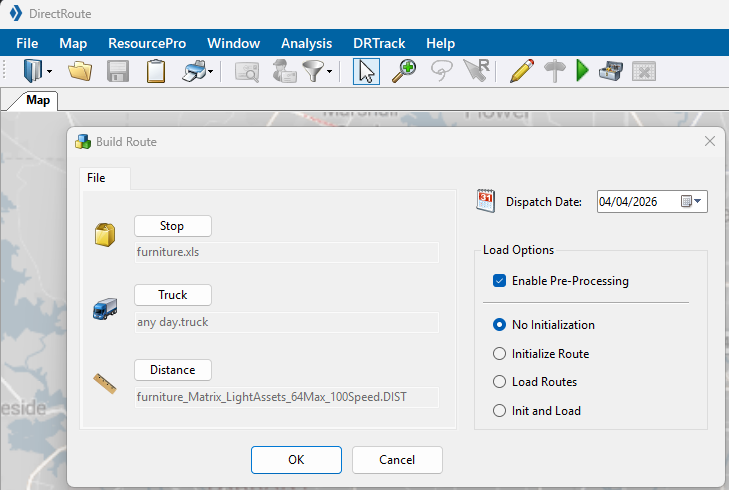 Figure 1. Regular Route processing options
-
-
Priority — Create a new manual Priority Route
-
Selective — Start a new manual Selective Route
-
Multi-Vehicle Route Optimization API — Use the API to generate a new Route. See the Developer Portal for API information.
-
-
Open Drawing — Open any drawing files created and saved in DirectRoute.
-
Save & Reload — Save and re-initialize the solution (displays predetermined Routes in the Route Book).
-
Print (Ctrl+P) — Print the Route Book, Map, Stop file, or Truck file using the expanded menu.
-
Preferences — Change program settings/configuration of data files.
-
Generate Distance file — Generate a Distance file to calculate distance using the available mileage system rather than a straight line.
-
Async Distance File Tasks — Alternative method to create a distance file, which allows licensed users to start multiple distance file generation tasks simultaneously. The Async Distance File Tasks button displays the progress of these submitted tasks. If blank, no tasks have been sent.
-
Update Stop file — Update the Stop file with data from another Stop file.
-
Extract — Create a Stop file with an extract from an order management system.
-
Run Post Process — Start the Post-processing actions selected in corresponding Preferences — pass Orders/ Routes in an upload file (UPL), pass Orders/ Routes to DRTrack, and/or print the Route Book upon completion of the routing process.
-
Export to DRTrack — Send Route information for purposes of tracking vehicles and routes through the DRTrack module (additional license required).
-
Recent Files/Recent Projects — Select recently completed files and/or projects.
-
Recent User Data Directory — Quickly switch to another recently used data directory, instead of switching via File > Preferences > File Names/Paths. Stores up to 10 recent directories.
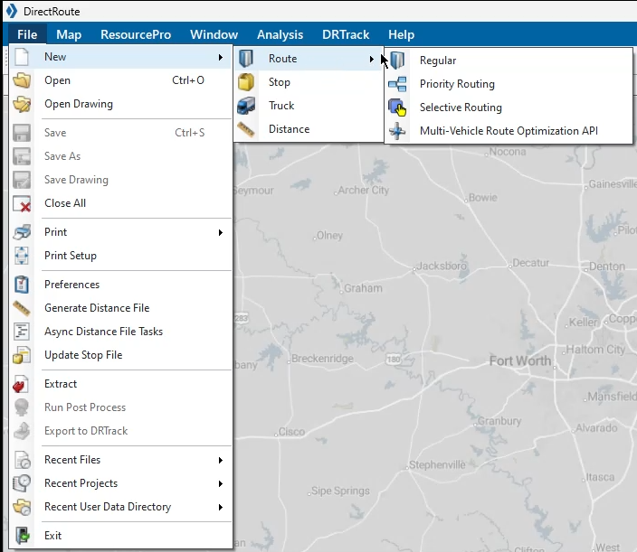 Figure 2. File Menu
-
- View Menu
-
Opens a Route Book, and various information windows found within, along with the option to consolidate Routes or view reporting. The View Menu is made available in Routing mode. See the Route Book Section for details.
-
Route Book — Open a new Route Book.
-
Consolidate Routes — Combine Stops using a unique identifier, location proximity, or a fixed time. Visit Preferences under Routing > Consolidate Settings to set defaults.
-
Stop Filter — Search Stops by column name and key word, exclude phrases, and view saved queries.
-
Solutions Statistics — View statistics and totals for the entire routing solution of the selected Route Book.
-
Stops Grid — Explore every Stop detail in the Route Book. Filter unloaded Stops.
-
Miles by State — View the Miles by State report after generating turn-by-turn directions. See Reports for details.
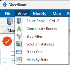 Figure 3. View Menu
-
- Modify Menu
-
Provides many of the same Routing actions available in the Toolbar. The Modify Menu is made available in Routing mode. See the Modification & Optimization section for descriptions of the available actions. View the Lasso capabilities under the Map & Map Tools section
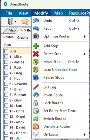 Figure 4. Modify Menu
- Map Menu
-
Links actions for the Map window including view customizations and zoom functions. Additional tasks include:
-
Default Map — Set a custom, Default Map (area and zoom level) to be displayed each time a DirectRoute session is started.
-
Map Themes — Set the type of map to display - Transportation, Datalight, Datadark, Terrain, or Satellite.
-
Map Region — Set one of nine specific map regions using a DirectRoute-called web service:
-
PCM_NA = North America
-
PCM_EU = Europe
-
PCM_OC = Oceanic
-
PCM_SA = South America
-
PCM_ME = Middle East
-
PCM_AS = Australia
-
PCM_AF = Africa
-
PCM_WW = Worldwide
-
-
Plot Map Points — Set a specific address or latitude/longitude to geocode/ plot on the map. Also includes the following:
-
Add New Point — Add lines to the info box to enter additional addresses.
-
Clear All — Clear all the Stops from the map and the Stops list.
-
Zoom to All Stops — Zoom the map to all the Stops.
-
Close — Close the Map Point info box.
-
Geocode — Geocode the address entered.
-
Add Stop — Add the Stop(s) to the map.
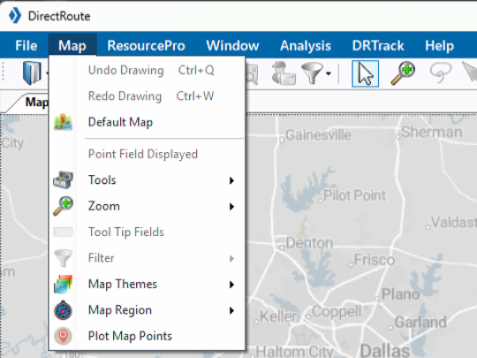 Figure 5. Map Menu
-
See Map Tools for further details
-
- ResourcePro Menu
-
Provides access to ResourcePro functions. ResourcePro is a DirectRoute add-on module. Additional license may be required. To learn more about this menu’s actions and tools, see the ResourcePro User Guide.
-
Schedule — Launch the ResourcePro build that assigns trucks and drivers to selected Routes using the algorithm and set Scheduling parameters.
-
Initialize Project — Select the XLS path and file containing the Route, Driver, and Truck Assignments to start using the Initialize Project tool. This tool displays the current assignments to simulate the way the fleet is currently operating; however, it turns off the scheduling algorithm.
-
Lock and Load Project — Manually schedule one or more drivers and lock in their schedule, then use the algorithm to optimize the load across the remaining drivers and Routes.
-
Resolve For Tractors — Resolve for tractors only, without changing any of the Route start times (unless manually overridden). Use this function after Routes are manually reassigned and start times changed.
-
Schedule Trailer — Recalculate the solution, scheduling trailers independent of drivers and/or tractors, with the requested minimum hours between Routes.
-
Make Truck Equal to Drivers — Recalculate the solution, making the number of Trucks used equal to the number of drivers used.
-
Time Violations — Select time violations. Set Violations are displayed as green. Any time a violation occurs in a Route, it is displayed red (e.g., wait time, return time, time window).
-
Start Time — Change the Start Time on a Route.
-
Zoom — Zoom in or out of the Truck or Driver Gantt charts.
-
Export — Export driver and truck statistics to a spreadsheet file (Driverstats.xls, Truckstats.xls); saved in the data folder.
-
Display Label — Choose which labels are displayed on the Gantt charts (e.g., Truck number, Start Time, Truck ID, Route Number, or None).
-
Violations — Ignore specific violations, rather than correct them, when manually reassigning resources and a truck or driver violations occurs.
-
Chart Preferences — Set options for the ResourcePro chart (e.g., working days and start/end times).
-
Lock Start Time/ Day — Prevent the Route’s start time and day from being altered during any modification or optimization process.
-
Push Route ETAs to DirectRoute — Find the optimal number of drivers and tractors needed to achieve an even number per day across the routing solution. Then, send this information to be used with DirectRoute’s cost-saving algorithm.
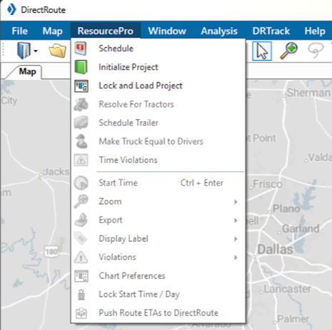 Figure 6. ResourcePro Menu
 -
- Analysis Menu
-
Launches the following tools:
-
Cross Dock vs Doc section — Allows users to evaluate customer service areas, where multiple methods for distribution exist, and determine the best network design solution based on cost.
-
Cross Dock Statistics — Provides the estimated linehauls required from the distribution center to each cross dock (based on the evaluation).
-
-
Scenario Manager section — Allows users to run various Route scenarios for analysis without affecting the integrity of the original Route or Route files.
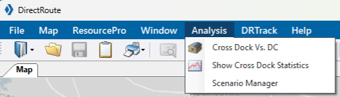 Figure 7. Analysis Menu
-
- DRTrack Menu
-
Supports several options to upload and download information between DirectRoute to DRTrack such as:
-
Upload/ Download Account Master — Upload an open Account Master file, in DirectRoute, to the Branch of choice in DRTrack. Download Account Master data, from any Branch in DRTrack, to DirectRoute.
-
Upload/ Download Truck Master — Upload an open Truck file, in DirectRoute, to the Branch and Profile of choice in DRTrack. Download a truck Profile, from a Branch in DRTrack, to DirectRoute.
-
Upload/ Download Email accounts — Service available if Email Manager is configured in DRTrack.
-
Export to DRTrack — Transfer the open Route project from DirectRoute to the default Branch in DRTrack.
-
Export Master Routes to DRTrack — Transfer the open Master Route project, from DirectRoute, to the default Branch and Master Route Profile in DRTrack.
-
Download Master Routes — Transfer the active Master Route Profile for the default DRTrack Branch to DirectRoute.
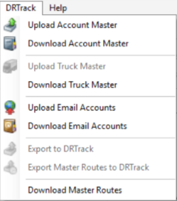 Figure 8. DR Track Menu
-
- Help Menu
-
Access to documentation, support, feedback channels, and important information concerning the software program and system in use.
-
Documentation — Link to DirectRoute support documents.
-
Contact Support — Contact information for Trimble MAPS Support.
-
Content tools — Access the HTML Help file, for DirectRoute guidance.
-
Ideas & Improvements — Connect to a customer feedback portal to share ideas and identify pain points.
-
Download — Download items from the ClientCenter.
-
About — Identify the software license and version number, date, and primary application path in use by the operating system.
-
API Key — Click on the button for copy / paste purposes.
-
Lease Expiration — Indicates when the next authentication is required (approximately every 24 hrs.).
-
Licenses — Display the account’s active licenses.
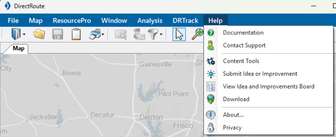 Figure 9. Help Menu
-
-
Toolbar
The DirectRoute toolbar contains shortcut icons for performing frequent or critical tasks. Some of the icons/ actions are not available (grayed out) unless specific files are open, certain actions have been completed, or one of the licensed add-on modules is in use.
In addition to the familiar open, save, and print file actions, DirectRoute offers the following Routing actions.
ACTIONS
Book — Create a new Route
-
Regular — Create a Dynamic Route using the user-modified preference settings.
-
Priority Routing — Activate the Priority Routing tool.
-
Selective Routing — Reopen the Truck and Stop Grids when working with Routes created with Selective Routing.
-
MVR Optimization API — Pass a wide range of parameters as inputs using the same DirectRoute algorithms with this Restful API. Visit the Developer Portal for more information.
Clipboard — Copy a portion of the map and drawings to the Windows clipboard or a Word application.
Geocode by Zip — Find the latitude and longitude of records within the Stop file and Truck file, then update the records according to their center of the 5-digit zip code.
Geocode by Address — Locate the latitude/longitude of records within the Stop file and Truck file according to their exact address and ZIP+4.
Stop Filter — Enable selection of files for preprocess functions and the unique records from the Stop file for display on the map.
Map Zoom — Focus on any selected area of the map using the Zoom icon in the toolbar. There are pre-defined zoom options as well as customizable zoom functions.
Lasso — Select a Stop (or group of Stops) on the map for editing, loading, or unloading purposes with this tool. See Map & Map Tools section for details.
Manual Routing — Choose specific Stops to Route rather than using the automated process. See the DirectRoute User Guide to learn how to generate a manual Route.
-
Drawing Tools — Open drawing tools to create borders and text on the map.
-
Get Directions — Provide turn by turn directions for each selected Route, while in the routing mode.
Generate Route Directions on Route Edit — Regenerate directions if Routes are edited after they were initially produced. New directions appear on the lower left side of the screen when ready.
External Utilities — Produce additional configuration utilities for some users. Options are defined in utils.config.
Match Sequence Number to Shape — provide Minimize All Info Grids — Minimize all open info panels in the Route Book and create tabs for each on the left side of the screen.
Application Selector — Move effortlessly between DirectRoute and the application’s add-ons with the dropdown menu.
Save Layout — Organize, resize, and save your viewing preferences.
Map & Lasso
MAPS
DirectRoute uses maps provided by PC*Miler[1] Web Services. The application calls the web service to locate and retrieve the most current maps.
-
Requires an active internet connection each time a new DirectRoute session is started.
-
An inactive connection results in a gray map screen.
-
All routing functions remain available without the maps or internet if the mileage system selected for routing is set to PC*Miler Direct.
-
Maps are only cached while a project is in session.
If the internet is lost during a session and Then The DirectRoute session is not terminated
The map is restored
The DirectRoute session is terminated
The map is deleted
-
To learn more about the DirectRoute map and its tools, use these quick links or scroll below:
- DEFAULT MAP
-
-
The default view shows the entire United States.
-
Users can adjust the map view to display a specific area each time a session is started.
-
Pre-defined options — USA, Region, 5-digit zip, or City (Cities are limited to the maps installed in your system).
-
Customizable functions:
-
Zoom percent — Control the zoom-level percentage applied when the
+and-keys are used. -
Zoom To — Set a specific map width to zoom to when the left-click action is taken.
-
Double Click — Select the type of action that occurs when you double-click the mouse.
-
-
Search using coordinates (latitude/longitude), in the bottom left corner of the map. These change as the cursor is scrolled across the map.
-
After any map manipulation, click on Restore (Ctrl + R) to return to the map default.
-
-
Point Field — Set/ change the information displayed for each geocoded Stop on the map, when the zoom level is 100 miles or fewer.
-
Any column heading in the Stop file can be displayed.
-
-
Use the Scroll Bar, at the bottom of the map, to zoom in (left) or out (right) on the map.
-
Filter which records to display — Use the filter options on the right for additional refinement.
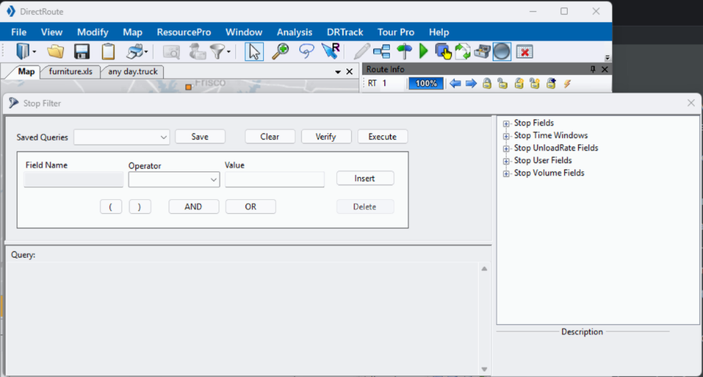 Figure 10. Stop filter
-
- STOP INFO ON THE MAP
-
Detailed Stop info appears in the Stop Info box when the cursor hovers over the Stop.
-
When Stops are tightly grouped on the map, all Stop info is displayed in one box.
-
The footer lists the number of Stops loaded vs. total Stops displayed.
-
The custom, user-defined fields, in the center of the box, are always white text on black background, but the Header color indicates a Stop’s status:
-
Yellow — Unloaded Stop prior to routing; no footer
-
Red — Unloaded Stop in route; footer reads Unloaded
-
Blue — Loaded Stop in route; footer message displays Route, Leg, and Sequence #
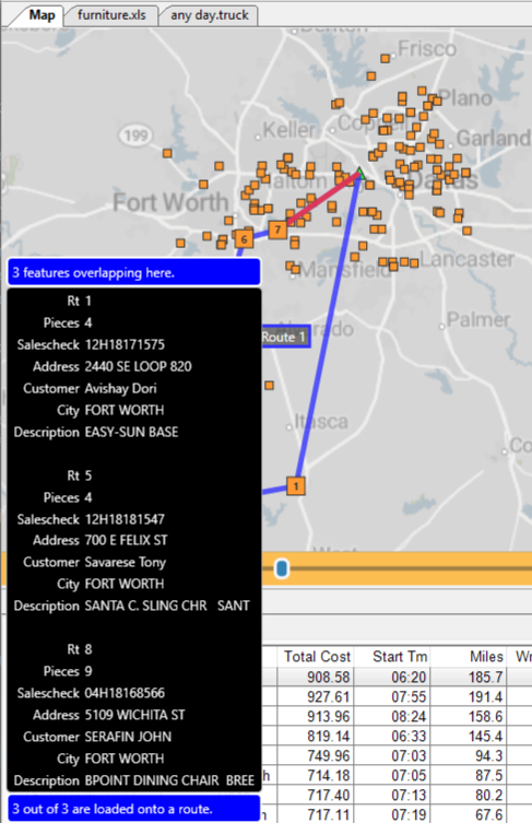 Figure 11. Stop info box with multiple Routes
-
-
Zoom to Selected Spreadsheet Record — Select a specific Stop from the spreadsheet and focus it on the map. Requires either geocodes or zip code to work
-
- MAP COLORS AND SYMBOLS
-
Color-coded Stop symbols are chosen and saved in a Route file (e.g., Stop file), then represented on the map when that Route file is open. With 30+ symbols and 40+ colors to choose from, numerous combinations can be used to customize the map display.
Use the symbols and colors to:
-
Identify types of Stops (e.g., circle = convenience stores and square = grocery store).
-
Identify customers who receive deliveries on specific days of the week (e.g., red = Mondays, yellow = Tuesdays).
Referring to the figure below, the Stop file indicates that all Stops should be orange squares. The Truck file indicates the Truck profiles should be lime green arrows.
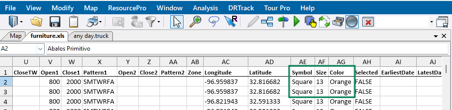 Figure 12. Stop file color & symbol indicators
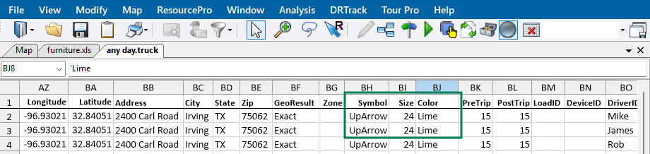 Figure 13. Truck file color & symbol indicators
-
See also the Drawings & Boundaries section under Advanced Routing Tools.
- LASSO
-
The Lasso Tool enables the selection of a Stop or group of Stops (records) from the map and options to:
-
Load or unload and move Stops to other Routes
-
View Stop details including the number of Stops lassoed, the number of items, and its retail value
-
-
Manually build Routes
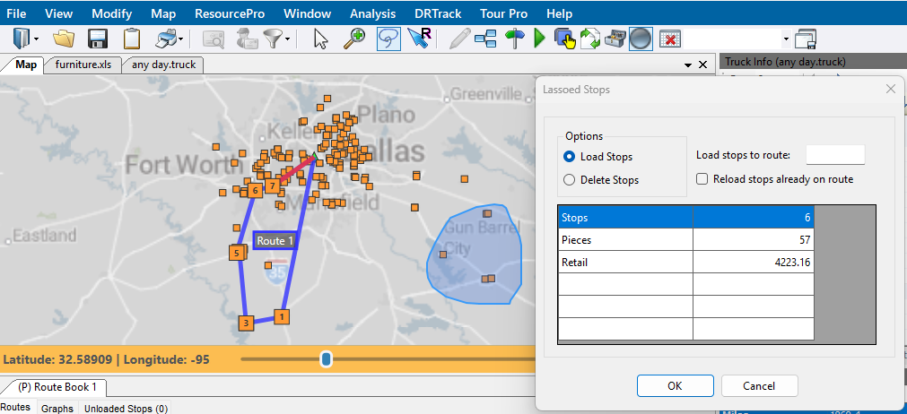 Figure 14. Lasso tool options
-
Route Book
The Route Book is a fully customizable reporting engine that can be exported to Microsoft Excel. A Route Book is created each time a new routing solution is completed. It provides a detailed picture of each individual Route and a custom Route report (summarized data) for the entire routing solution.
By default, the Route Book window appears below the map, to the left of the Stop and Truck file windows. This window can be closed or moved to a tab for easy toggling between a larger map.
-
The first Route Book opened appears as (P) Route Book 1 (on the first tab). P identifies it as the primary Route Book.
-
If subsequent Route Books are opened at the same time, each additional Route Book is numbered (e.g., Route Book 2, Route Book 3).
In addition to the map, there are three main windows. Use these quick links to skip to a specific section or scroll below.
-
Map Filter Window (with Stop, Solution, and Differential Info)
ROUTE BOOK WINDOW
There are three tabs of interest in the Route Book window: Routes tab, Graphs tab, Unload Stops tab. Explore each tab below.
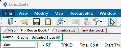
Routes Tab
The Routes Tab summarizes each Route including the Route number, TruckID, Cost, Start and Work times, and Miles in customizable columns. Data can be re-ordered by dragging the column into position. There are also several means to modify a Route. These actions are described in the section below.
-
Sum Column — List of clickable Route numbers and drivers. Click on Sum for the totals of all the Routes, or select one or more Routes to view specific statistics.
-
Show Gauges — Provides a quick view of total work time, drive time, and capacity levels on each Route.
-
Work Time — Percentage of work time completed on the Route
-
Drive Time — Percentage of drive time completed on the Route
-
Capacity — Percentage of the truck’s capacity used (e.g., 100%) vs the capacity that has been unloaded thus far on the Route (e.g., 25%).
-
If the Route capacity is exceeded, the gauge color changes from blue to red.
-
Use to determine if a Stop(s) need(s) to be added or deleted from a Route.
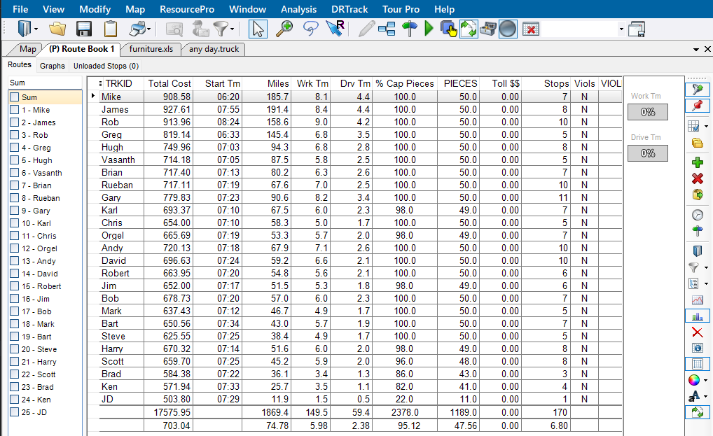 Figure 16. Route Book - Routes Summary
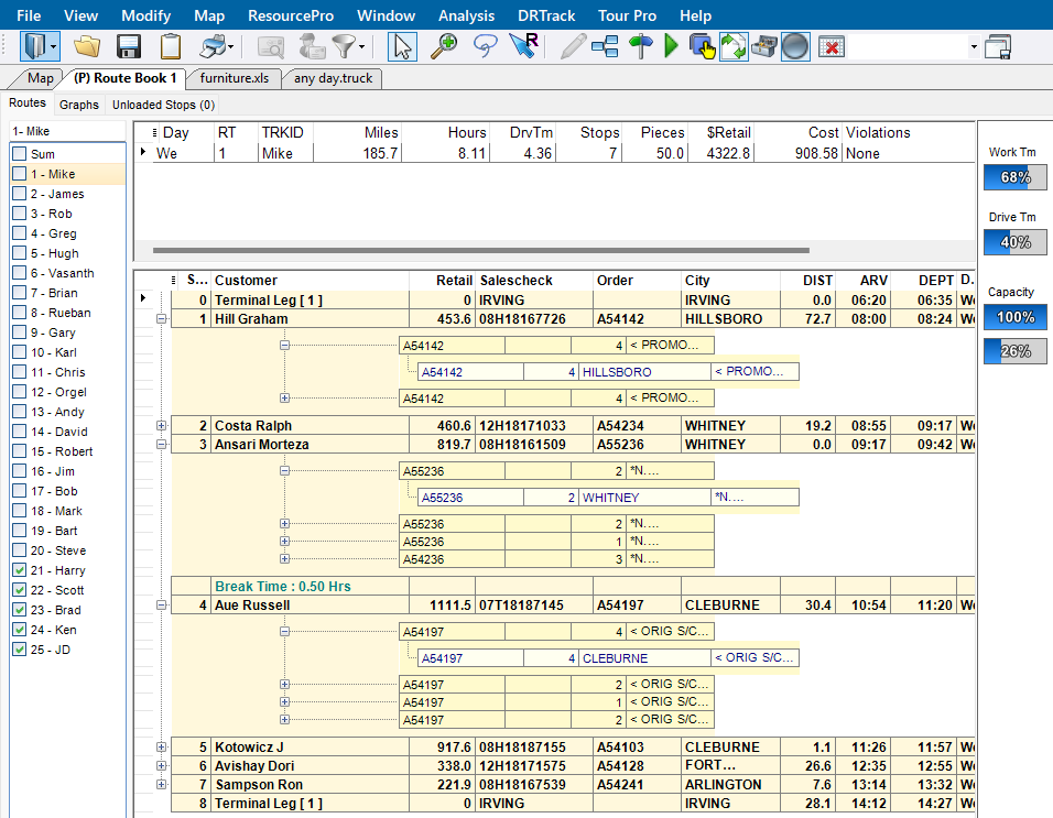 Figure 17. Route Book - Specific Route Summary view
-
-
- Route Tab Actions
-
There are two separate places where Route/ Route Book actions can be taken from this Route tab. See the Modifications & Optimization section for additional Route modification options.
-
Toolbar — Shortcuts to common Route modification actions found in the vertical toolbar on the right side of the window.
-
Right-click — Actions accessed by right-clicking on a Route in the table.
-
- Route Tab Toolbar
-
-
Show on Map — Show / Hide the selected Routes on the map.
-
Show unloaded to map — Show / Hide the unloaded Stops for the Routes selected on the map.
-
Detailed Grid Status — Opens/ Closes the Route Table to specific line item, order, or Stop information:
-
Expand to Order
-
Expand to Line Item
-
Collapse to Stop
-
Collapse to Order
-
-
Show All Expansions — Opens/ Closes all collapsible sections.
-
Add Stop — Includes an unloaded Stop to a Route.
-
Delete Stop — Deletes an unloaded Stop from a Route.
-
Move Stop — Manually move one or more Stops from one Route to another. See also Optimize Between Routes in the Route Optimization section.
-
Change Start Time — Sets the time for the Route to begin.
-
Hide/Show Directions — View/ hide turn-by-turn driving instructions generated for the Route selected.
-
Route Book Fields — Populate a list of all the Route Book fields displayed in the Route table (organized by Route file).
-
Route Book Filter — Filter by Route info fields and field results or use free-form text to filter without navigating through the entire filter workflow.
-
Report List — Select the style of report to view from a dropdown list.
-
Show / Hide Route Graph — View/ Hide the Route graph that appears below the Route table.
-
Delete Field — Hi-light the column and click on the Delete Field (X) to remove the field from the Route table.
-
Show / Hide Order Line Item Headers — View / Hide the order and line item headers within the Route table.
-
Show / Hide Line Grids — View / Hide the grid lines within the Route table.
-
Set Colors — Select the colors for each item on the map - Stop / Order / Line.
-
Set Font — Select the desired font for each item on the map - Stop / Order/ Line / Header / Summary.
-
Sync with Other Windows — Ensure the changes made in one window are carried over to all other windows.
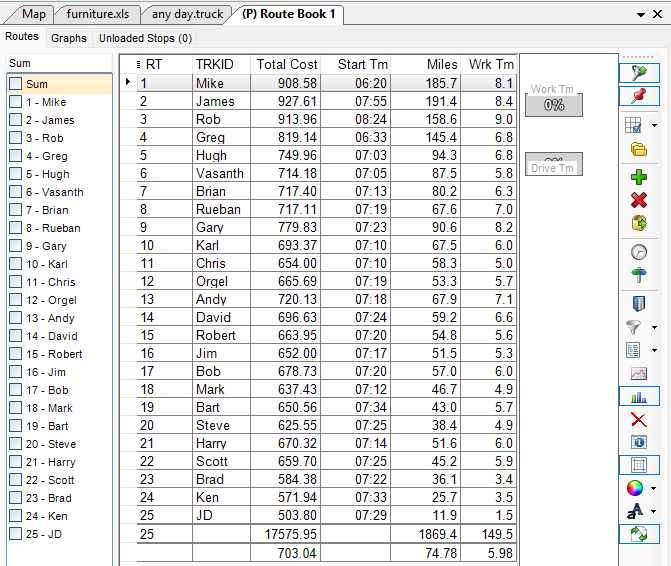 Figure 18. Route Tab Toolbar
-
- Right-Click Actions
-
-
Add Stop — Include an unloaded Stop on a Route.
-
Delete Stop — Delete an unloaded Stop from a Route.
-
Delete Range — Delete a selected series of Stops from a Route.
-
Delete All — Delete all Stops from a Route.
-
-
Move Stop — Manually move one or more Stops from one Route to another. See also Optimize Between Routes in the Route Optimization section.
-
Split Stop — Manually split a Stop, by quantity or percentage, on a Route.
-
Invert Route — Reverse the sequence of Stops on a Route.
-
Relay Route — Create a line-haul from an alternative warehouse, dock, yard, or domicile to the actual warehouse.
-
Relay by Destination — Create a line haul from the remote domicile to the main depot (destination).
-
Relay by Truck — Create a line haul from a truck dispatch location that is not the remote domicile or depot.
-
-
Set Route Start Time — Set the time the Route should begin.
-
Switch Routes — Switch trucks between Routes.
-
Unviolate Routes — Remove violation flags from Stops on a Route. E.g., A Stop violates a time window, but the user decides to deliver the Stop anyway. The command removes the flag, but it can change other settings.
-
Lock Route — Limit the number of alterations the optimization actions can have on a Route. Users can lock a single Route or multiple Routes at one time.
-
Convert Stops to Shipments — A Transportation Modeler feature that lets users create a multi-shipment Route rather than a multi-Stop Route based on the origin, transportation mode, and method, among other considerations.
-
Switch Mode — Swap transport modes, based on the capacity of the truck in use, for most accurate cost and transit time calculations.
-
TL to LTL — Switch mode from Truck Load to Less than Truck Load.
-
LTL to TL — Switch mode Less than Truck Load to Truck Load.
-
-
Delete RT Book Field — Hi-light the column and right-click on the Delete Field (X) to remove the field from the Route table.
-
RT Book Properties:
-
Color Route Book Stops — Select the color of the Stops to be displayed in the Route Book.
-
Color Route Book Trucks — Select the color of the Trucks to be displayed in the Route Book.
-
Set Auto Width — Create a default column width for the Route Book.
-
Show Route Book Toolbar — Show / Hide the Toolbar within the Route Book.
-
Show Route Book Header — Show / Hide the Column Headers within the Route Book.
-
Set Font — Select the font style and size to be used within each report of the Route Book.
-
Set Color — Select the font color to be used within each Stop, order, line, and header.
-
Show Headers (order & detail) — Show / Hide the column headers for orders and its details.
-
Show Gridlines — Show / Hide the gridlines within the Routes table.
-
-
Show Directions — Show / Hide the directions generated for the selected Route.
-
Show Gauges — Show / hide quick view icons for total work time, drive time, and capacity levels on each Route.
-
Show Graph — View/ Hide the Route graph that appears below the Route table.
-
Show RT Book Fields — Populate a list of all the Route Book fields displayed in the Route table (organized by Route file).
-
Show Stop Detail — Show Stop data for any Stop on any Route. Select the specific Stop in the Route Book to highlight the Stop.
-
Skip Empty Routes — Allow empty Routes and Trucks from being included in the Routing solution. When they are skipped, they are not visible.
-
Hide Empty Routes — Hide any empty Route on the map that was included in the Routing solution.
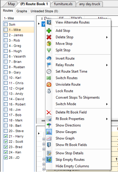 Figure 19. Route Tab actions
-
GRAPHS TAB
The Graphs tab visualizes the Routes that are summarized on the Routes Tab.
-
It uses the color indicators selected in the Stop and Truck files (e.g., these files indicate that all Stops are orange and all Truck IDs are lime green).
-
Hover over any colored box for an explanation (e.g., drive time, or Stop information).
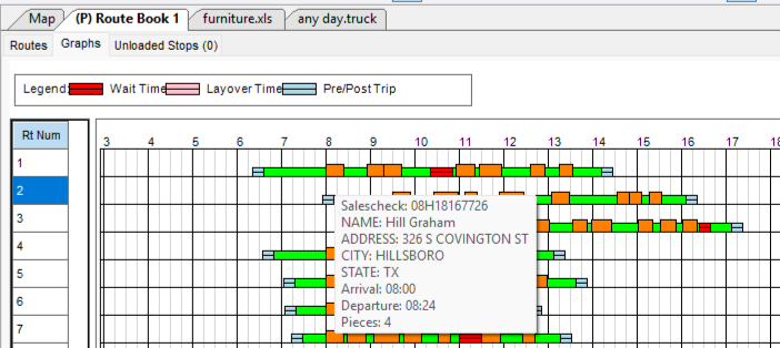 Figure 20. Graphs tab with hover-over information
 -
Right-click any line for options to turn off Route label, zoom, show/ hide legend, or print.
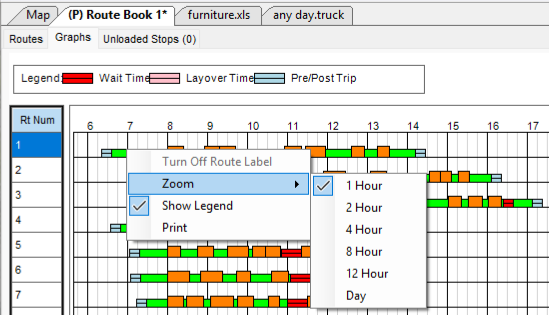 Figure 21. Graphs tab with right-click options
UNLOADED STOPS TAB
The Unloaded Stops Tab lists any Stops that have not been loaded to a Route in a table form.
-
Right-click on any line to view the Unloaded Stop Reason
-
Options:
-
Ignore Empty Candidate Routes — Hides trucks without Stops
-
Ignore Loaded Routes — Hides trucks with Stops
-
Show All Routes — Show/ Hide all Routes
-
-
Show Unviolated Candidate Routes Only — View Routes without violations
-
Evaluate All Routes — Un-filters the truck listing to show all trucks (deprecated)
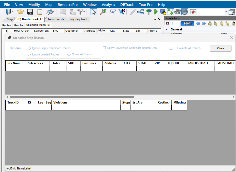 Figure 22. Unloaded Stop Reason
-
Check out this Unloaded Stops video for more info.
TRUCK & ROUTE INFO WINDOWS
The Truck & Route Info Windows are broken into two unique tabs found at the bottom of the window - Truck Info and Route Info.
-
If this window is pinned, the tabs move from a horizontal format at the bottom of the window to a vertical tab along the top right side of the screen.
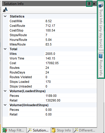 Figure 23. Truck & Route Info window pinned
Truck Info Tab
The Truck Info tab displays the Truck file data for a specific Route and/or Stop and truck-related preferences.
-
Click on the fields to update.
-
Locate the Truck record with the row number, and use the arrows to scroll through the rows
-
Use the Toolbar to organize and format the window:
-
Pin window to a right-side panel.
-
Sort fields by Category or alphabetically.
-
Expand or Collapse All categories.
-
Favorite any attribute to highlight it in the Favorites section (Star icon).
-
Move up or down categories.
-
Sync info to all Windows (after an edit has been made).
-
Use the letter A icon to customize the fonts within all Info boxes on the right-side of the screen.
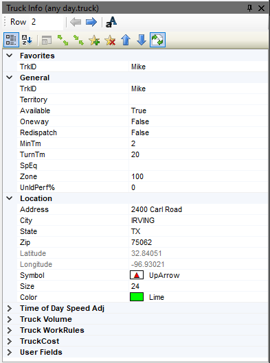 Figure 24. Truck Info Categories & Toolbar
 -
Route Info Tab
The Route Info window displays the Route data for the specific Route appearing in the Route Book and various route-related preferences.
-
Click on the fields to update.
-
Pin window to a right-side panel.
-
View Capacity percentage — The percentage displayed pertains to the primary capacity or volume.
-
Scroll through Routes on the map using arrows.
-
Lock and unlock one, all, or selected Routes — Locks the selected Route(s) on the map to keep it visible when scrolling. This lock does not prevent modifications.
-
Right-click on a Route in the Route Book Summary Table to lock the desired Route from modifications.
-
-
More Options (lightning bolt) — Opens a secondary toolbar that mirrors Truck Info Tab’s toolbar.
-
Use the letter A icon to customize the fonts within all Info boxes on the right-side of the screen.
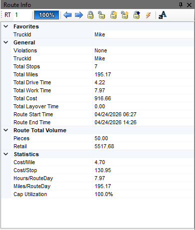 Figure 25. Route Info Categories & Toolbar
MAP FILTER WINDOW
In the Map Filter window, the data updates based on the Route or solution selected and are displayed in tabs across the bottom of the window.
-
If this window is pinned, the tabs move from a horizontal format at the bottom of the window to a vertical tab along the top right side of the screen.
There are four tabs of dynamic information. Use the quick links, or scroll below to review tab information.
- Unloaded Stops Tab
-
The Unloaded Stops tab has a section for both the Routes and Unloaded Stops. If there is at least one unloaded Stop, the following options are available:
Routes — Check the box to hide the active Route plus any locked Routes. Unloaded Stops — Use the dropdown to filter the Unloaded Stops by the Stop User Fields setup in Preferences > Configuration (e.g., filters on the status of certain engine parts).
- Solution Info Tab
-
The Solutions Info tab displays the statistics and totals for the entire routing solution of the selected Route Book. This tab can also be viewed in a spreadsheet.
For instance, referring to the figure below:
-
There are 24 Routes over 24 days
-
170 Stops loaded and 0 unloaded
-
It costs $8.52 per mile
-
It took just under 6 hrs. per Route
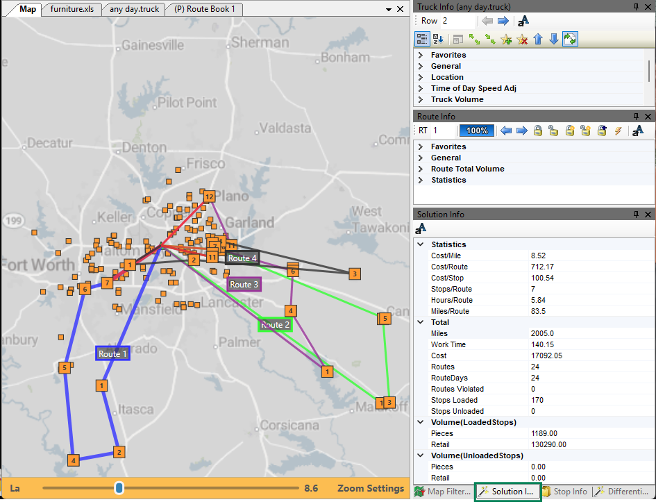 Figure 26. Solutions Info Tab
 -
- Stop Info Tab
-
The Stop Info tab focuses on a specific Route number in the Route Book rather than the entire routing solution.
Use the toolbar to:
-
Scroll through the Routes, using the arrows to the right of the Route number, to view the dynamic info.
-
Zoom to the Route on the map using the magnifying glass.
-
Sync information automatically to the active Stop.
-
Use the letter A icon to customize the fonts within all Info boxes on the right-side of the screen.
-
Organize the Stop preferences by category (default) or alphabetically.
-
Expand or Collapse All categories and use the up / down arrows for quick views and organization.
-
Favorite/ un-favorite any attribute to highlight it in the Favorites section (Star icon).
-
View the Stop Detail table — Opens a pop-up window with customer, order, and description specifics.
-
Show Focus Circle on the Map — Adds a black circle around the corresponding Stop on the Map
-
Pin the tab to a right-side panel.
-
Referring to the figure below, we can see Route 3
-
Contact information including order number
-
Has a fixed time of 15 mins
-
No special equipment codes
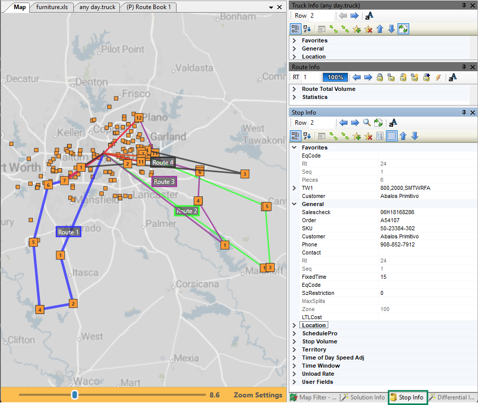 Figure 27. Stop Info Tab
Differential Info Tab
This tab displays the differences in values (e.g., miles, work time, cost) when one or moves are made on a Route.
Click on the column headers to toggle between the following:
-
DRStats — Values achieved immediately after DirectRoute completes initial Route loading.
-
TransStats — Difference in values between the last move and current move.
-
AggStats — Adds the value differences of all moves.
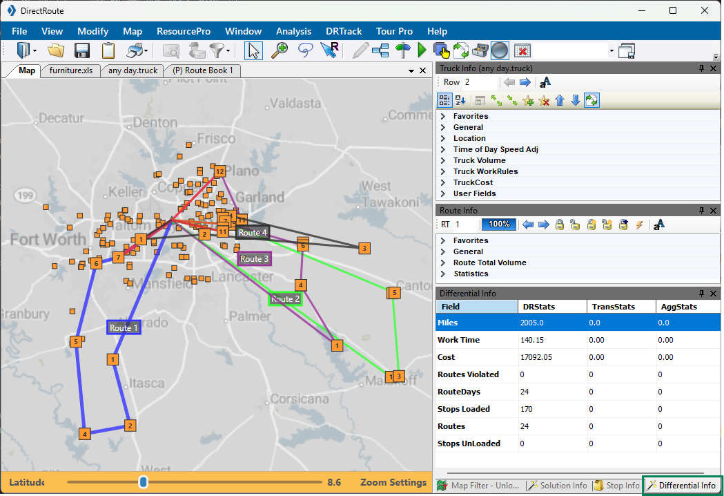 Figure 28. Differential Info Tab
Reports
The Route Book reports are broken down into three areas, each having unique, customizable formats.
-
Multiple report formats can be saved in the user’s Data Dictionary (the location of the files and folders).
-
If any report is changed, even if it is formatting only, all reports must be copied to the data dictionary.
Report Description Summary
Solution-level statistics addressing each Route.
-
Displays a list of all the Routes created in the project including Route numbers, Truck IDs, Route totals (e.g., miles, hours, Stops), cumulative totals, and averages.
-
Displays when Sum is selected in the left column.
-
Default report when the Route Book opens.
Detail
Route-level data covering each unique Route and all the Stops on it.
-
View consolidated Stops by clicking the
+next to the Stop. -
Displays when the Route# is selected in the left column.
Miles by State
Total miles by state for all Routes (calculated when generating directions).
-
Set Generate Route Directions preference to TRUE.
-
Download as a .csv, .tab, or .xls File.
-
The Route Summary tab — Lists the totals for each Route separately.
-
The State Summary tab — Lists the totals by state.
-
Free Miles — Free miles traveled (non-toll roads) for each state
-
Toll Miles — Toll road miles traveled for each state
-
Toll Cost — Costs for each state
-
Total Miles — Total miles for each state
-
To learn how to generate and customize reporting, see the DirectRoute User Guide.
-
Files
DirectRoute runs off fleet (truck) and customer delivery information provided in Routing files. DirectRoute requires the following to function properly. See the DirectRoute User Guide for requirements and instructions for creating files.
-
Account Master File
-
Stop File or Daily Order File
-
Truck File
- MERGE UTILITY
-
External Utilities contain an additional tool, Merge Utility, which enables the merger of two or more Stop files into one cohesive Stop file, even if all the columns are not the same or do not match.
-
Helpful for users with add-on modules (e.g., SchedulePro, TerritoryPro).
-
Requires the use of the Util.config file.
-
If you do not have this file, or are not able to access it, contact Trimble MAPS Support.
-
-
DirectRoute Basics
Learn about DirectRoute’s functions and capabilities within the sections below:
About DirectRoute
DirectRoute is a domicile-centric[2], automated fleet routing program that can be used as a standalone application or with licensed add-on modules and integrations. The application uses multiple intuitive algorithms, customer-selected preferences, and seamless integration with ERP software to build routing solutions for nearly any scenario. DirectRoute can also:
-
Improve capacity usage
-
Reduce empty miles
-
Save time and manual effort through automation
-
Evaluate potential routing scenarios
-
Download order and customer files
Explore further in the Use Cases section below.
- ROUTING DATA
-
Before DirectRoute can assist in developing Routes, it must understand your routing environment and potential deliveries (routing data). This routing data is provided within Route files (e.g., Stop, Truck, and Distance files).
During the Route-build phase, DirectRoute considers the following data among others:
-
Truck availability, capacity, and special equipment
-
Driver availability, assignments, and work restraints
-
Travel time, layovers, speed adjustments, and distance
-
Delivery time and date windows; arrival, departure, and unload times
-
Fixed Routes, Stop and order volumes, and consolidations
-
Algorithms and optimization settings
-
Truck file and Stop file parameters
-
User-selected routing preferences
-
- EXAMPLE
-
The following is an example of how DirectRoute builds a typical Route with the required files (or downloads from an order Management System).
The system:
-
Reviews the Route files for routing data to establish the who, what, when, and where for the solution (e.g., customer, location, and delivery windows).
-
Uses the routing parameters and user preferences, defined in each project, to determine additional variables like work rules, Route modifiers, and special equipment requirements.
-
Loads the Stops and builds the Route(s).
-
Summarizes and provides key statistical data pertaining to each Route including:
-
Total miles for each Route
-
Time required to complete the Route(s)
-
Total volume (e.g., weight, cubes)
-
Cost of the Route
-
Combined totals (variables above) of all Routes and their averages
-
The user can then:
-
View the Route(s) and modify as needed.
-
Save the Route(s) and print, if necessary.
-
Upload Routes to an Order Management System, GPS tracking system, or other.
-
Display (and print) detailed delivery schedules with arrival/departure times.
-
Maintain key Route statistics (e.g., total drive and work time, mileage, capacity, costs).
-
- USER DATA
-
DirectRoute collects non-PII data such as button clicks, sessions by user, and number of Routes created.
Uses Cases & Benefits
DirectRoute can be used as a standalone application or with add-on modules and integrations for the following uses.
- SINGLE-, MULTI-DAY, & SPECIAL ROUTES
-
The application was built with diverse fleet routing in mind. Review the Advanced Routing Tools section for a full list of capabilities.
-
Select from 5 advanced algorithms to create Routes for a variety of shipping needs, including complex, multi-day Routes.
-
Add a specialty or optimization algorithm for refined and enhanced solutions.
-
-
Manage daily exceptions, varying order volumes, and capacity changes with Route modification tools.
-
Handle special scenarios like backhauls, one-way deliveries, and re-dispatches with ease.
-
Apply specific Route modifiers, customer constraints, and driver preferences for route-building guidance and back-office visibility.
-
- MULTI-DEPOT OPERATIONS
-
Multi-depot operations generally happens in two main phases:
-
Planning — Determining optimal depot locations (e.g., deciding between a Cross Dock and a Distribution Center).
-
Routing — Connecting these depots efficiently (linehaul), often facilitated by Relay Routes.
Routing multiple locations simultaneously can be tricky. Without geographical constraints or boundaries, the algorithm tends to produce suboptimal results. DirectRoute offers diverse services and tools to aid in these challenges through all phases.
-
Relay Routes — Multi-depot Route that creates a line-haul from an alternative warehouse, dock, truck yard, or domicile to the actual warehouse (referred to as the remote domicile). The Routes are started from the remote domicile to the delivery point.
-
Cross Dock vs DC — This tool allows users to evaluate service areas, where multiple methods for distribution exist, and determine the best network design solution based on cost. It answers questions like, Is it cheaper and faster to ship directly from the distribution center or complete a line haul to a local warehouse for final delivery?
-
Boundaries & Drawings — Tools used to define and lock territories that can be assigned to Trucks and Drivers to create consistent, familiar routines within a wide network of customers and depots.
-
Use the TerritoryPro add-on to create and adjust territories based on a host of shipping constraints.
-
- TURN-BY-TURN DIRECTIONS
-
Turn-by-turn directions can be created after the Route is built. The directions are acquired through DirectRoute’s mileage system that adheres to all routing preferences selected for the routing solution. There are two separate options for direction generation:
-
Trimble Maps — Uses the default Trimble Maps mileage system
-
PC*Miler — Uses the PC*Miler mileage system for licensed users
-
- CUSTOMIZABLE REPORTING
-
All DirectRoute reports can be customized in the Route Book to focus on the information you want and disregard the data you do not.
-
Add or remove columns of information.
-
Drag columns to arrange the order of information displayed.
-
The software automatically populates the data for the selected columns.
-
Download, print, and share solutions-level summaries; detailed, Stop-inclusive reports; or a miles-by-state review.
See the Reports section under Application Components for additional details.
-
- MODEL BUSINESS CHANGES
-
Use DirectRoute for more than Route building. Evaluate operational costs and assess hypothetical changes before committing to any business-altering decisions.
-
Scenario Manager — An advanced tool that provides analysis of various Route scenarios without affecting the build of the original Route or Route files.
-
Cross Dock vs DC — Evaluation tool for service areas with multiple distribution methods to determine the best network design solution based on cost. Use before committing to a business model.
-
LTL Costs — Feature helps with shipping decisions - Is it more cost-effective to deliver a small order with your private fleet, or hire a third party / LTL to ship it? Calculate for cheapest mode of transportation.
-
Boundaries & Drawings — Use boundaries for operational efficiency — Calculate the statistics of records within/ outside the territory to determine which customers can be serviced based upon warehouse capacity, and build Sales territories or Routes based on area and sales.
-
Baseline vs Future — Create a baseline — The actual spend, capacity, Route, and service-levels numbers to compare to potential futures. Model one or many scenarios by altering volumes, network design, routing rules, and user preferences. Then, determine if a future scenario is worth pursuing — How big are the savings? What are the impacts to operations? What changes need to be made to materialize the new future?
Comparing a baseline to futures can also:
-
Surface dependencies and risks — Allows users to assess variables needed to carry out the potential future (e.g., process adoption measures, regulatory limits, IT delivery timelines, or capital and investments needs).
-
Align across functions — Create a common language, with a shared baseline and explicit future goals, so tradeoffs are understood (e.g., cheaper but slower or higher cost but better service), roles can be assigned, and metrics can be created.
-
-
Routing Algorithms
DirectRoute provides five distinct routing algorithms, also known as Load algorithms, to fit your operational needs. No matter which algorithm is selected (Preferences > Algorithm Settings > Algorithms), the Route is created in a similar manner — The algorithm starts its process each time by finding the furthest unloaded Stop from the truck depot. That is the seed point of Route 1. So, Route 1 typically gets sent to the furthest point away, for every customer on every Route. The Load algorithms also consider the following:
-
Max number of Stops per Route
-
Normal daily start time of the vehicle
-
Total work time (the shift) for each vehicle
These options listed below, like the Furthestin algorithm, control the sequence of the Stops rather than the geography of the Route. Users can add a specialized or optimizing algorithm for additional refinement and enhancements.
Review available algorithms using these quick links or scroll below:
Routing (Load) Algorithms |
Optimizing Algorithm |
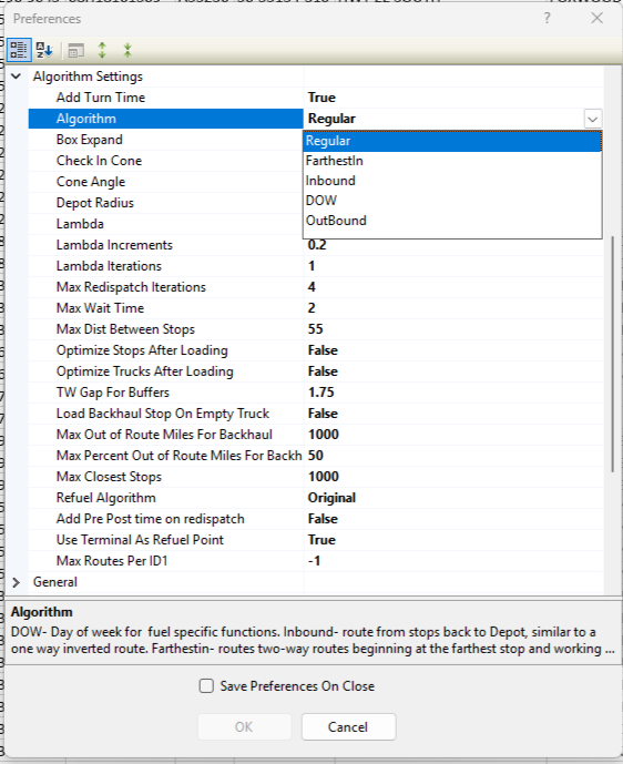
- REGULAR
-
Generates round trip routing solutions from the depot out to the furthest Stop and back to the depot. It begins making deliveries shortly after departing the depot. It prioritizes by geography to create a flower petal-shaped Route pattern.
-
Most popular algorithm, supporting 95% of the DirectRoute customer base.
-
Most used within the Final Mile industry.
-
- Example
-
Scenario — Should I use the DOW algorithm or the Regular algorithm?
-
There is a week’s worth of orders that need to be Routed.
-
There are orders with specific delivery windows for several days.
-
Stops close to the distribution center need to be delivered first based on their orders and delivery windows.
Using the Regular algorithm, the Route is created geographically focusing on the farthest Stop first. By doing so, it loaded the orders at the end of the Route first and left 16 Stops unloaded because of capacity issues. Those 16 Stops, close to the depot, have delivery windows for the beginning of the week. If they made it on the Truck, they would not be delivered until late in the Route and miss their delivery window.
Using the Day of the Week algorithm, the Route is created after reviewing the entirety of orders and prioritizing based on the given delivery windows. The orders that need to be delivered first are not left unloaded, rather paced on the Route to meet the delivery needs. The algorithm may then pull in a later date’s order if it is geographically appropriate and cost-effective to do so.
If the orders did not have specific delivery windows, either Routing algorithm works.
-
- FURTHESTIN
-
Creates routing solutions starting from the farthest Stop and routes back to the depot creating a narrower Route pattern than the Inbound algorithm.
- INBOUND
-
Creates a routing solution that begins at the furthest Stop and routes back to the depot similar to an inverted Route or Furthestin. This Route pattern is a bit wider than the Furthestin.
-
Does not calculate the distance from the depot to this furthest Stop (Starting point).
-
It is used without One-way Routing mode because these trucks return to depot.
-
Often used to avoid conflicts with traffic.
-
- DOW
-
The DOW (Day of the Week) algorithm is designed for situations when the demand exceeds the available capacity. It focuses on the Earliest Date and Latest Date columns in the Stop file to prioritize deliveries and routes the most important orders first. It may include orders not due until a later date if it is geographically and cost-effective to do so.
- OUTBOUND
-
Creates a solution that starts at the closest Stop and routes out to the furthest Stop last. Generally results in an empty truck at the furthest Stop allowing for backhauls.
-
Creates either a one-way or a two-way Route, but not both within the same Stop file.
-
Can be used when One-way Routing mode is set to True in the Truck file.
-
-
Does not calculate the distance from the last Stop back to the depot (two-way Routes).
-
The Route ends once the last Stop is complete making it compatible with over-the-road business models.
-
-
Use with the BH EQcode in the Stop file to create a backhaul.
-
- EXAMPLE
-
When comparing algorithms, if Stop A is the furthest Stop from the Depot:
-
Regular — Stop A is in the middle of the Route
-
FurthestIn — Stop A is the first Stop
-
Inbound — Stop A is the first Stop
-
Outbound — Stop A is the last Stop
-
DOW — Stop A is placed on the Route based on the dates set in the Stop file
-
SPECIALIZED LOAD ALGORITHMS
There are two specialized load routing algorithms for specific industries: Refuel and Tanker.
- REFUEL
-
The Refuel algorithm is used when refuel (replenishment) points are enabled.
-
Distance Based — Tracks Route capacity and adds refuel points only when capacity is available and 30% of work time is left in a Route. This option removes refuel points when not needed.
-
Although Original is the default, users should only use Distance Based when using the Refuel Algorithm.
-
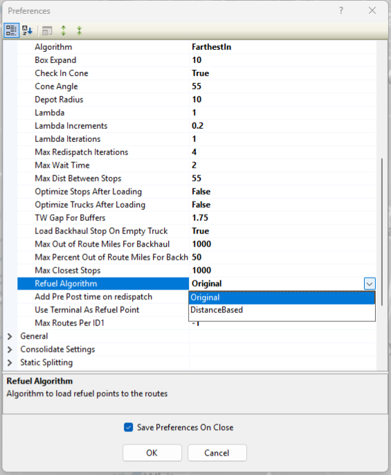 Figure 30. Refuel Algorithm setting
 -
- TANKER
-
The Tanker Algorithm and assignment logic help optimize trailer compartment utilization. It is used when multiple products, in various order quantities, are loaded together onto compartmentalized trucks for either a pick-up or delivery Route. It is only applicable if the Tanker algorithm is enabled.
-
The process of building a Route remains the same with or without the Tanker algorithm enabled.
-
The Tanker logic considers the volume and weight of loaded totes, tanks, and spaces.
-
Tanker Route results are returned in the Route Book and can be viewed on the Summary page, individual Route pages, and the Info boxes.
-
A Tanker chart displays color-coded items loaded, the number of tanks and totes filled on each Route, and remaining capacity levels.
-
The Tanker Algorithm uses the Stop and Truck files along with the following:
-
Tote file — Identifies each Tote in use and its maximum capacity levels. The volume fields in the Tote file must match the volume fields in the Product Ratio file.
-
ToteID — A number ID assigned to a specific tote.
-
Gallons — The maximum gallon capacity of the tote.
-
Weight — The maximum weight capacity of the tote.
-
Cube — The maximum cube capacity of the tote.
-
Pallet — The maximum pallet capacity of the tote.
-
Available — Availability of the tote entered as TRUE or FALSE.
-
-
Product Ratio file — Contains the product code and the corresponding ratio (e.g., gallons) for each item loaded in a tote.
-
Product Code — Code/ name assigned to a specific product unit.
-
Gallons — The number of gallons in one product unit.
-
Weight — The weight of one product unit.
-
Cube — The number of cubes in one product unit.
-
Pallet — The number of pallets assigned to one product unit.
-
-
-
Tanker algorithm settings are required. See Tanker under Routing Preferences
-
Add a secondary algorithm for enhanced routing solutions.
- OPTIMIZATION
-
The Optimization algorithm is a secondary process that occurs after the load algorithm creates the Routes. The load algorithm constructs the Route based on parameters but does not attempt to improve the Route once it is built - that is the role of optimization. Optimization compares different scenarios to find cost savings and improve the solution. This optimization process is also known as Box Expand. See this section to understand how the Box Expand settings alter how the optimization algorithm works.
-
Requires Cost fields in the Truck file to work effectively — mileage, fixed and hourly costs.
-
Adds a Penalty cost to the Route using the following formula: Total Penalty Cost = # of Violations * Penalty Factor * Cost Per Stop * Violation Penalty Weight.
-
Routing Preferences
Routing preferences, or parameters, help DirectRoute determine how to route based on various user-determined constraints such as work rules, travel restrictions, delivery windows, or available equipment. Depending on your routing environment, some settings may not be used. Routing Preferences:
-
Supply the software with necessary information about your routing environment and the type of results expected in the routing solution.
-
Identify specific data fields, volume types, and delivery windows used in the Truck and Stop files.
Upon installation, the assigned Appian Implementation and Training Consultant helps identify and update all settings that best fit your specific routing environment.
PREFERENCE SETTINGS
The Preferences window can be sorted by category (default) or alphabetically, and sections can be collapsed and expanded using the icons in the window’s toolbar.
-
Ensure the Save Preferences on Close box is checked for a worry-free experience.
Explore the Preference categories below:
• Defaults |
• DRTrack |
||
• Extract |
• Import |
||
• Other |
• PC*Miler |
||
• Routing |
• Tanker |
||
• Upload |
ModeSelection preferences have been deprecated.
- CONFIGURATION
-
Configuration preferences specific to Truck and Stop files.
Table 3. Configuration preferences Configuration Example Applied to Stop & Truck files ID1
Acct #
A unique field to identify a Stop (e.g., customer#, account#, invoice#)
ID2
Order #
Optional secondary field identifying a Stop (e.g., order#, SKU#)
ID3
item #
Optional tertiary field for identification
Name
Customer Name
Account number or identification
Address 2
Building #
Optional secondary address info (e.g., dock#, door#)
Contact
John Doe
Contact name for delivery
Phone
555-222-1234
Contact phone number for delivery
Volumes
Collection
Volume type used in the Stop file. Can be any quantity type (e.g., weight, cube, pallets, cases).
-
If no type is entered, the software loads all Stops on one Route until it reaches the maximum Stops per Route, as defined by the user.
Stop User Fields
Collection
Optional, user-defined fields in the Stop file. Use to collect info for reports, display in Route file (e.g., Comments, style, description) 20 fields available
Truck User Fields
Collection
Optional, user-defined fields to display in the Truck file. Use to collect info for reports and display in Route file (e.g., driver, shift, maint, Cat) 20 fields available
Number of Time Windows
2
The number of Time Windows in use for the Stop. 2 is default (1 - 10 available)
-
See Time & Speed-based Adjustments for more info.
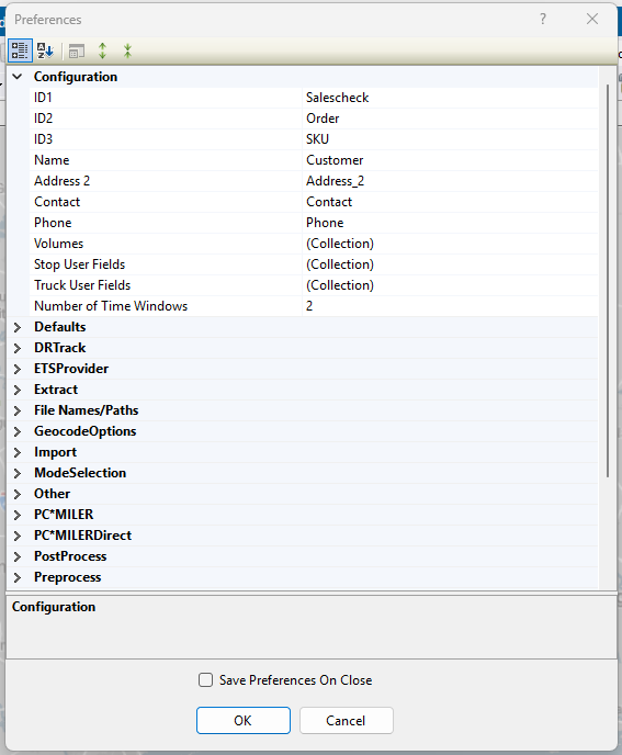 Figure 31. Configuration Preferences
 -
Return to top of Preferences
- DEFAULT
-
Default options applied during the extract process. These preferences apply to each Stop unless otherwise indicated in the Stop and Truck files. Use the files when any customer requires a value different from the default value.
Table 4. Default preferences Defaults Example Applied to All Stops Time Window
Collection
Use this field when all the Stops on the Route have the same delivery Time Windows. See Time & Speed-based Adjustments for more info.
Fixed Time
15
Leverage this field to indicate a standard, required time (in minutes) that all vehicles must spend at the Stop (in addition to unload rate) to account for paperwork or other activities.
-
Visit the Consolidated Stops for info on consolidations by fixed time
-
View Time & Speed-based Adjustments for more Fixed Time details
EQ Code
LG-BH-002
Apply this field when all the Stops on the Route require the same equipment code (e.g., liftgate)
-
See special Equipment Codes section for more details
Unload Rates
Collection
Utilize this field when all the Stops on the Route can be unloaded at the same rate (volume per hour)
Zone
110
Use when applying zone-based speed adjustments to account for areas with possible slow-downs (e.g., construction zones, dense traffic areas)
-
View Time & Speed-based Adjustments for more info
Earliest Date
1 Jan 2016
Use when all Stops on the Route have a delivery window starting on the same date. This is known as the Earliest Date eligible for delivery
Latest Date
3 Jan 2016
Use when all Stops on the Route have a delivery window ending on the same date. This is known as the Latest Date eligible for delivery
Early Buffer
.25
Use when Time Windows are applied. This is the extra time allowed before the delivery window opens. This creates an early delivery at a penalty cost (Enter as decimals in 15 minute increments e.g., .25 = 15 mins)
Late Buffer
.50
Use when Time Windows are applied. This is the extra time allowed after the delivery window closes. This creates a late delivery at a penalty cost (Enter as decimals in 15 minute increments e.g., .5 = 30 mins)
Penalty Cost
50
Apply when Time Windows and Early/ Late Buffers are in use. This is the fee assessed when the delivery time window is violated
-
The penalty is prorated and a value of 60 is suggested, equaling $1 per minute of buffer time used
Max Splits
2
Utilize when each Stop on the Route is allowed to be split. This indicates the maximum number of times any Stop (volume) can be split
-
When Apply Defaults is set to True, the Max Splits value is applied to each Stop
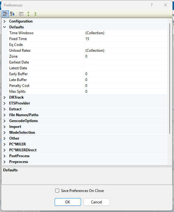 Figure 32. Default Preferences
 -
Return to top of Preferences
- DRTRACK
-
Settings for licensed DRTrack users to identify URL paths and IDs for uploading Routes.
Table 5. DRTrack user preferences DRTRack Example Explanation DRTrack URL
URL to DRTrack site. Used for uploading data/files
Company Name
Johnson Tile
Used for importing and exporting
DRTrack Username
Username for DRTrack
-
Set a Username and Password to ensure only authorized users pass data to and from DRTrack
DRTrack Password
Password for DRTrack
DRTrack Proxy Server
Name of proxy server, if used, to filter internet traffic
DRTrack Proxy Port
Your Proxy server port
DRTrack Proxy Username
Your Proxy server username
DRTrack Proxy Password
Your Proxy server password
DRTrack Timeout
10
System time-out value in minutes
Branch
(Collection)
Branch names, if used
Default Branch
Default Branch name
Profiles
(Collection)
Truck profiles, if used, for different routing days
Route Upload Version
5
Upload version number
Master Profiles
(Collection)
Master Profile names. More than one can be used
Shift
(Collection)
User-created Shift Name, From/ To, FromDayOffset/ ToDayOffset, and Truck profile information
Account Master Upload Version
1.0
Upload version#, if more than one is used
Use LoadID From Stop file
True / False
Default is False
Compression Method
None
File compression method
Manage Master Profile Routes
(Collection)
Start and end dates for each Master Profile
Skip Empty Routes
True / False
Default is True.
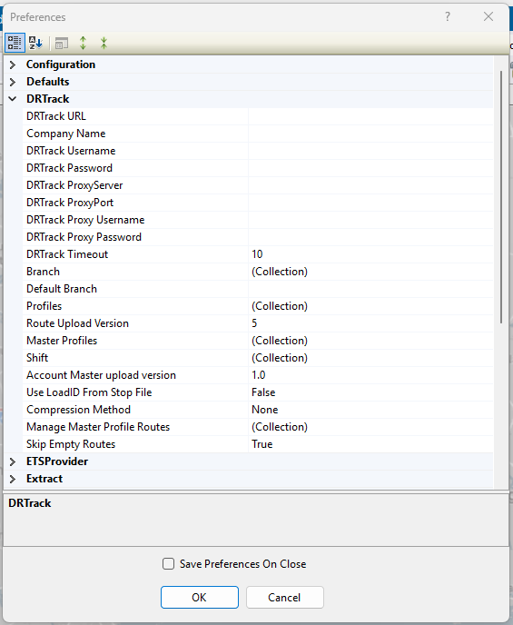 Figure 33. DRTrack preferences
 -
Return to top of Preferences
- ETS PROVIDER
-
Preferences for users of TMW, ETS, or TMW Innovative services
Table 6. ETS Provider preferences ETSPROVIDER Example Explanation TMW ETS
Truckmate
Select product family for interface. None is default
TMW Innovative Login
Username, Password, SCAC Code, and Service Version added under the dropdown menu
Return to top of Preferences
- EXTRACT
-
Data extract settings for use with an Order Management / Host systems.
Table 7. Extract preferences Extract Example Explanation Account Master file
Master.xls
Master file name
Append New Accounts to Account Master
True / False
Set to True to append the Master file with new account data found in the Extract file. Default is True
Extract Option
CreateStopFile
Creates a Stop file from the Master file with all account information, or updates Account Master file
Get Address from Account Master
True / False
Gets address information from the Master file. Default is False
Overwrite Address in Account Master
True / False
Set to True to overwrite address in the Master file with address from Extract file. Default is False
Primary Identifier
None
ID1 from Configuration setting
Secondary Identifier
None
ID2 from Configuration setting, if used
Tertiary Identifier
None
ID3 from Configuration setting, if used
Update Blank Account Master Fields
True / False
Set to True to update blank fields (existing customers only) in the Master file with data from the Extract file. Default is False
Use Defaults for New Accounts
True / False
Set to True to populate the default field settings (Time Windows, Unload Rates, etc.) to any new accounts in the Master file. Default is False
Zero Coordinates if Address does not match
True / False
Set to True to clear the latitude/longitude from the Stop file if the address in both the Master file and Extract file do not match. Default is False
Populate LoadID in Truck file
True / False
Set to True to copy LoadID from Extract file to Truck file when Routes are initialized. Applies when an Extract is performed with a new Route Build, and LoadID columns are populated. Default is False
LoadID Column Name
LoadID
Column that contains LoadID in Extract file
Interface
None
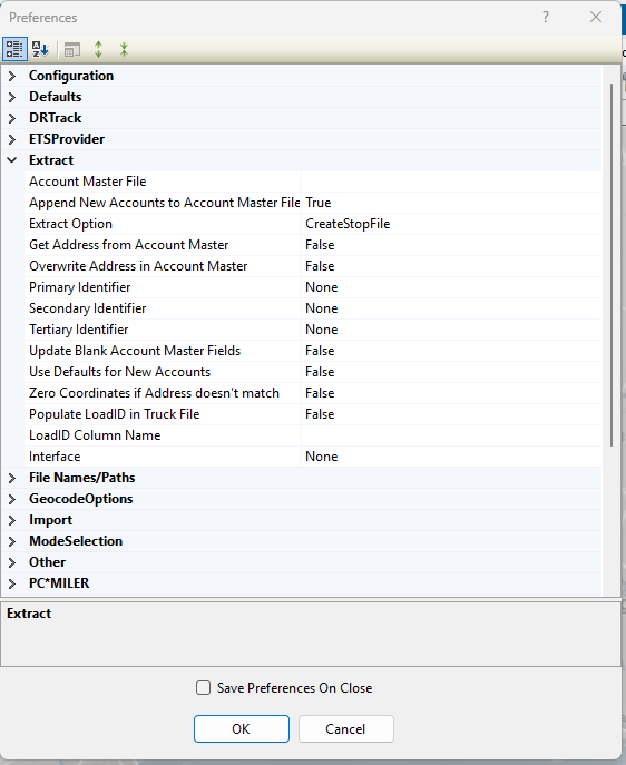 Figure 34. Extract preferences
Return to top of Preferences
- FILE NAMES/ PATHS
-
Settings for use with the location of file names and paths used in the routing process.
Table 8. File names & paths settings File Names & Paths Example Explanation User Data Directory
C:\Program files\Appian\DirectRoute\Data
Location of the user or project DirectRoute Data Folder
9-Digit Zip Directory
C:\Program files\Appian\DirectRoute\ZIP9 Data
Name and location of the ZIP9 Data file (See the DirectRoute folder created during the installation process)
Account Master file
C:\Program files\Appian\DirectRoute\Data\Acct Master file.xls
Location and name of the Account Master file
Base Map Directory
C:\Program files\Appian\DirectRoute\Base Maps
Location of the Map file. (See the DirectRoute folder created during the installation process)
Cross Dock file Path
C:\Program files\Appian\Direct Route\Data\Cross Dock.xls
Location and name of Cross Dock file
Custom Geocode file Path
C:\Program files\Appian\Direct Route\Data\Geo file.xls
Path to the Custom Geocode file
Drawing file Name
C:\Program files\Appian\Direct Route\Data\ Drawing file.drw
Path of the Drawing file
OBC Folder Path
OBC upload output folder path
Product Family file Path (*.xls)
C:\Program files\Appian\DirectRoute\PFFP file.xls
Select Product Family file for Tanker Algorithm (should contain populated ProductFamilyName column (mapped with TankSpEq column in Truck file) and populated ProductName column)
Relay file Path
C:\Program files\Appian\DirectRoute\Data\Relay file
Path to the Relay Truck file
Upload file Name
Upload file
Enter the name of the Upload file
Upload file Path
C:\Program files\Appian\DirectRoute\Data\ Upload file
Path to the Upload file
Upload Format file (*urp)
URP file name and location. Input removes prompt during every upload session
Z1 Path
C:\Program files\Appian\ DirectRoute\Address Cleanup\Z1.DAT
Name and location of the Z1 file (See the DirectRoute\Address Cleanup folder)
Z8 Path
C:\Program files\Appian\ DirectRoute\Address Cleanup\Z8.DAT
Name and location of the Z8 file (See the DirectRoute\Address Cleanup folder)
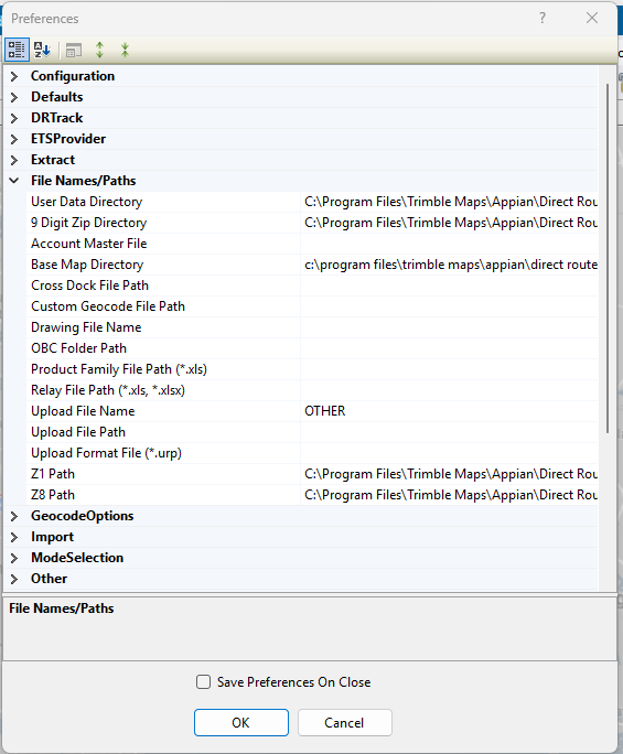 Figure 35. File names & paths preferences
Return to top of Preferences
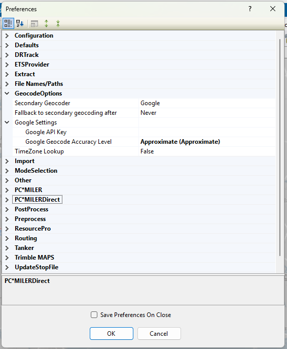
- GEOCODE OPTIONS
-
Selections for secondary Geocode processes and options (e.g., Google).
Table 9. Secondary Geocode preferences Geocode Options Example Explanation Secondary Geocoder
Google
Select Google to validate DirectRoute’s geocode results or to obtain Canada or Australia geocode results. Limited to 2,500 requests per 24hrs/ 10 requests per sec.
-
Enter None if no secondary Geocoding process is used.
Fallback to secondary geocoding after
Uncertain
Set to anything other than Never to use Google. Use these options to dictate when Google, as a secondary geocoding source, is used:
-
Exact — DirectRoute’s result is Level 1 confidence or less.
-
Good — DirectRoute’s result is Level 2 confidence or less.
-
Uncertain — DirectRoute’s result is Level 3 confidence or less.
-
Zip — DirectRoute’s result is less than zip code accuracy. Result is the least accurate, placing a pin in the middle of the zip code area, which can be several miles off.
-
Failed — DirectRoute’s result is Level 4 confidence or less.
-
Always — Google is used every time a record is geocoded despite DirectRoute’s result.
Preferences when Google is the secondary geocode process
Table 10. Google preferences Google Settings Example Explanation Google API Key
800900700601
Alphanumeric API key issued by Google when user initiates a Google Maps account
-
By default, a key can be used from any server. It is recommended that you restrict the use of your key by IP address to servers that you administer.
Google Geocode Accuracy Level
Rooftop
The desired accuracy level:
-
Rooftop — Default. (High Accuracy) precise down to the street address.
-
RangeInterpolated — (Same Street) An approximation, usually on a road, inserted between two precise points, such as intersections.
-
Geometric Center — (Same Region) The geometric center of a street (polyline) or region (polygon).
-
Approximate — (Approximate) The result is approximate.
TimeZone Lookup
True/False
Set to True if you wish to have Google verify time zone. Default is False
Geocoding in Canada and Australia — Ensure the country code is changed each time to match the country (Preferences > Other).
-
Return to top of Preferences
- IMPORT
-
Preferences used to import XML files from integrated TMW Systems software.
Table 11. Import preferences Import Example Explanation Enable Order Selection
True / False
Set to True to download orders for next dispatch date + additional days. Default is False
Overwrite Quantity Fields
True / False
Set to True to not pass required fields. Default is True
Overwrite User Fields
True / False
Set to True to not pass User Fields. Default is True
Ignore Trucks passed in XML
True / False
Set to False to prompt the user to pick a Truck file. Default is True
Enable Preprocess
True / False
Set to True to enable Preprocess to run when importing from an XML file. Default is False
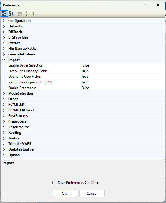 Figure 36. Import preferences
Return to top of Preferences
- OTHER PREFERENCES
-
Table 12. Mileage System, geocode files, and special maps files Mileage System Example Explanation Mileage System
Trimble Maps
Mileage System used with the software
-
Trimble Maps is default and recommended
-
PC*MilerDirect is used for offline DirectRoute
-
PC*Miler is used if the user is licensed for the PCM Connect utility and wants to connect to a stand-alone version of DirectRoute
Date Format
MM/dd/yyyy
Options are: MM/dd/yyyy, dd/MM/yyyy, MMMM dd yyyy, or yyyy-MM-dd
Time Format
Used to pass to a primary business system using an Upload file and to specify if the time, displayed in the Route Book, includes seconds
Custom Geocode file Path
C:\Program files\Appian\DirectRoute\Data\ Geo file.xls
Location of custom Geocode file, if used
Geocode file Col Identifier
CTY
Column name in custom Geocode file, to be examined when applying custom geocoding
Distance Options
Miles
Miles or Kilometers, used in map bar display
Coordinate Option
Decimal Degrees
Decimal degrees, (Degree:Minute:Seconds) used in the map status bar
Convert STP/xls file
True / False
Set to True to convert .STP and older .xls files to newer format
Find Street Layer
Example
Explanation
Major Road
Main Street
Name of the road
Street 1
Usa_dap
Street 2
Additional address identifiers e.g., apartment, suite, floor, or building number
Country
En-AU (English) Australia
Use with Google Maps API Geocoding and applicable country code, if needed
Company Name
Parks
Name
Auto-save solution after generating directions
True / False
Set to True to save solution after direction generation
Auto-save Route Book layout files
True / False
Set to True to save Route Book layout when the Route Book is closed
Clone Stop and Truck file while using the Save As option with the Route file
True / False
Set to True to save/copy Stop, Truck, and Route file, when using Save As option to close files. Copied files are assigned a new name, same as the Route file, while original Route files are left unchanged
Store distance entries in
file
Select file or database (PC*Miler Route type). If entries are stored in a database, use the following app settings in the exe.config file:
-
DistanceEntries = TRUE
-
ConnectionStringName = Name of the string configured
-
CompanyID = 1 (default)
Order Criteria
Example
Explanation
Query by User Field
Status
Enter each Stop User Field to enable filter for Stop selection
Query by Values
Ready / Not Ready
Enter all Values separately (e.g., Stop User Field = Status)
Stop Selection Color
Blue
Choose color for stop selection
Auto open Stop Grid on Routing
True / False
Set to True to automatically open the Stop Grip in a routing solution
Replenishment Point Name
TruckID
Choose refuel point name to be displayed. Default is TruckID
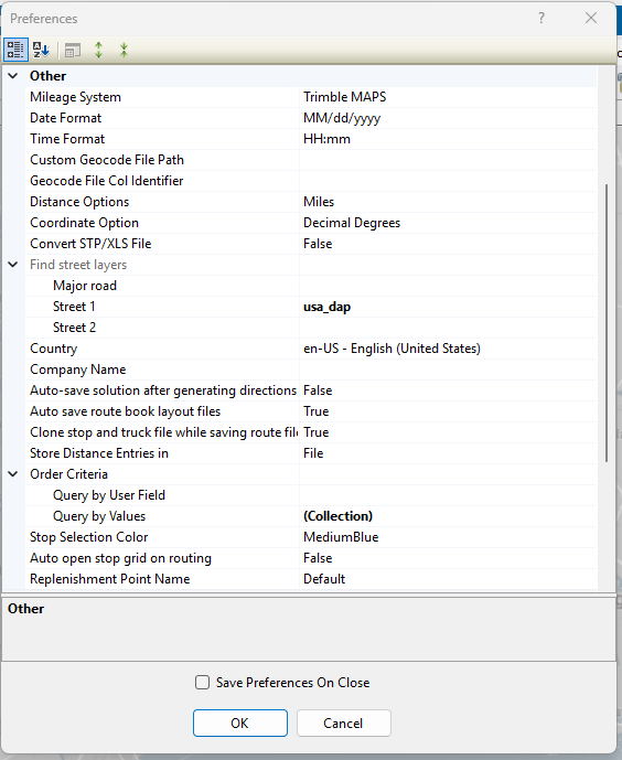 Figure 37. Other preferences
 -
Return to top of Preferences
- PCMILER
-
Routing and vehicle options for PC*Miler with a license
Table 13. PCMiler with a license PC*Miler Example Explanation Route across borders
True / False
Set to True to allow Routes to cross international borders. Default is False
Route Type
Practical
Options include: Practical, Shortest, or Fastest
Route Type option
Default
Options include: Default, National, Avoid Toll, or Fifty Three
Hazardous option
None
Options include: None, General, Explosive, Inhalant, Radioactive, Corrosive, or Flammable
Thread
Single
Set to Single unless generating a Distance file for multicore CPU, then set to Multiple
- PCMILERDIRECT
-
Routing and vehicle preferences for PC*Miler DIRECT without a license
Table 14. PCMiler DIRECT without a license PC*Miler Direct Example Explanation Route across borders
True / False
Set to True to allow Routes to cross international borders
Route Type
Practical
Options include: Practical, Shortest, or Fastest
Avoid Toll
True / False
Set to True to avoid toll roads when possible during the routing process. Default is False
Hazardous option
None
Options include: None, General, Explosive, Inhalant, Radioactive, Corrosive, or Flammable
Thread Count
0
16 max threads
Distance Generation Mode
Pair
Option to change how PC*Miler generates distance entries. Default is Pair
Vehicle Profiles
Collection
48’ Semi Trailer
Enter all vehicle profiles used in the Truck file to make available for selection as a Default Vehicle Profile
-
Options: Light Assets, Full-sized van, Double Trailers, Straight Truck, 48’ Semi Trailer, 53’ Semi Trailer, or Custom (PC*MilerDirect/ Vehicle Profiles)
-
Add additional, if necessary under Custom. Profile allows edit of vehicle height, length, width, weight limit, and # of axles (no less than 2)
Default Vehicle Profile
Only vehicles entered in Vehicle Profiles are available for selection.
Select the default vehicle profile to use during the Route building process
Map Region
Default Map Region
N/A (not used at this time)
Use Historical Traffic Data
-
Requires additional Appian licensing
-
Set to True to generate drive times and distances based on historic traffic time estimates and collected real-time traffic data, instead of DR’s calculated drive time/ distances
-
When not used, the system defaults to DR Drive Time (or other installed Mileage System)
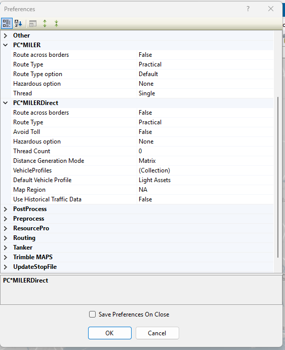 Figure 38. PCMiler and PCMiler Direct preferences
 -
Return to top of Preferences
- POSTPROCESS
-
Preferences that accelerate processes after a routing solution is created.
Table 15. PostProcess preferences Postprocess Example Explanation Upload
True / False
Set to True to pass Orders/ Routes in an upload file (UPL) after routing
Upload DRTrack
True / False
Set to True to pass Orders/ Routes to DRTrack after routing
Print Route Book
True / False
Set to True to automatically print the Route Book upon completion of the routing process
Return to top of Preferences
- PREPROCESS
-
Preferences that accelerate processes before routing, like UltraFast Distance Matrix and geocoding.
Table 16. PreProcess preferences Preprocess Example Explanation Distance file
Example
Explanation
Generate Distance file
True / False
Set to True to generate Distance file during Preprocess
Use DirectRoute Drive Time
True / False
Set to True to use DirectRoute’s internal algorithm settings and map files rather than a Distance file
Maximum Speed
65
Maximum allowable speed by vehicle on a route
Speed Adjustment
100
Adjust drive time by [X] factor ( e.g., 100 is baseline, 120 increases drive time by 20%)
Distance File
Select the existing Distance file to use in preprocess
Local Options
Example
Explanation
Minimum Distance Between Stops
0
Minimum distance the software will compute distance between Stops
Maximum Distance Between Stops
800
Maximum distance the software will compute distance between Stops
Generate 2-way entries for Stops less than (x miles)
5
Add a return distance, between two Stops, within [X] miles of each other
Generate 2-way distance entries
True / False
Set to True to calculate distances To and From Stops
Stem Distances Only
True / False
Set to True to calculate distance between the Terminal and City where the Stop is located (not the Stop itself)
In Cone
True / False
Set to True to ensure only Stops within the Angle or Radius may be added to the selected Route
Overwriting Existing Entries
True / False
Set to True to overwrite any Distance file in the DirectRoute Data folder
Within Territories
True / False
Set to True to generate a Distance file with distances listed between EqCodes of the same type
Route Across National Border
True / False
Set to True to allow Routes to cross Canada and/or Mexico borders. If False - Prevent Routes from crossing borders but may result in more miles.
Commercial Restrictions
True / False
Set to True to for Prophesy to use only roads permitted for commercial vehicles
Avoid Toll Roads
True / False
Set to True to keep Trucks from using toll roads
Threading
Single
Multicore CPU - set threading to Multiple, otherwise set to Single
Distance file
Location to save Distance file (generated during pre-process)
Use Mileage System Drv Time if it is > DirectRoute Drv Time
True / False
Set to True to use an optional, installed Mileage System. Uses the optional Mileage System’s drive times if those drive times are greater than DirectRoute’s calculated drive times
UltraFast Distance Matrix
Example
Explanation
Profile Name
North_American_Auto
Select one of nine North American and European vehicle types to match your fleet
Geocoding
Example
Explanation
Geocode Stops
True / False
Set to True to Geocode Stop file before routing
Clean Address
True / False
Set to True to call the Address Clean up module to clean the records prior to Geocoding
Skip Geocoded Records
True / False
Set to True to skip any records that have been previously Geocoded
Color Code Stops
True / False
Set to True to color codes Stops
Update Address, City, and Zip
True / False
Set to True to update corrected Address, City and Zip
Apply Boundary
Example
Explanation
Apply EqCodes to Stops
True / False
Set to True to apply EqCodes to Stops
Drawing file name
NorthEast Dallas
Name of Drawing file used
Overwrite Existing EqCodes
True / False
Set to True to overwrite existing EqCodes
Apply Defaults
Example
Explanation
Apply Defaults
True / False
Set to True to enable the Stop filter selection during the routing process (activates the Stop filter pop-up menu)
Overwrite Existing Entries
True / False
Set to True to overwrite existing entries in Stop file
Fixed Routes
Example
Explanation
Run Fixed Routes
True / False
Set to True to ensure Stops are matched to Trucks based on the fields selected to get Route assignments
Truck file Matching field
Trk ID
Select a field from the Truck file
Stop file Primary Matching field
Trk ID
Select field in the Stop file that corresponds to the field in the Truck file
Stop file Secondary Matching field
Driver
Select the field in the Stop file that corresponds to the field in the Truck file
Copy Sequence
True / False
Set to True to copy sequence number from the selected field to the SEQ field
Stop file Sequence field
Select the field that has the sequence number
Get DOW Sequence Code Based Upon Pattern 1
True / False
For fuel-specific functions
Overwrite Route and Sequence
True / False
Set to True to overwrite existing Route and Sequence, if any, already in the Stop file
Generate Route Directions
True / False
Set to True to generate Route directions after Routes are built
Enable Stop filter
True / False
Set to True to enable the Stop filter during the Route building process
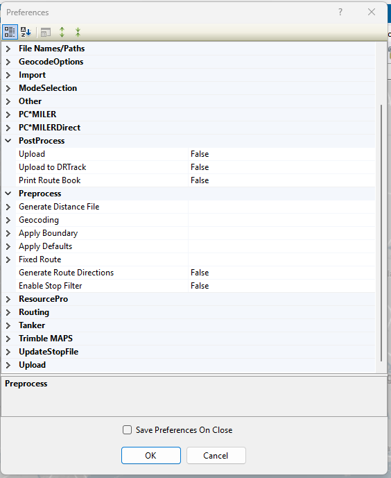 Figure 39. Pre & PostProcess preferences
Return to top of Preferences
- RESOURCEPRO
-
Licensed ResourcePro users can set their ResourcePro Scheduling Parameters to override the DirectRoute factory default settings.
Table 17. ResourcePro preferences Scheduling Parameters Example Explanation Ignore User Start Time
True / False
Set to False if the user changes a Route’s start time (using the clock icon in the DirectRoute Route Book) and wants ResourcePro to honor that time without changes (i.e., do not ignore my user set dispatch time)
Scheduling Algorithm
Best Algorithm
There are 3 options: Drivers First, Trucks First or Best.
-
The Drivers First — Algorithm prioritizes reducing the driver count over the number of trucks
-
The Trucks First — Algorithm prioritizes reducing the number of trucks over the number of drivers
-
Try the Trucks First algorithm if it is believed that exceptionally tight time windows is the reason for a suboptimal answer
-
-
Best — (default) Algorithm is a combination of Drivers First and Trucks First. It provides a solution with the lowest number of total assets (truck or driver)
Ignore Truck Start Time
True / False
Set to False, for the algorithm to honor the times set in the Truck file (EarStart and LatStart)
Min Hours Between Routes (Vehicles)
1
Time needed for a truck to prepare for the next Route (e.g., refuel time)
Min Hours Between Routes (Drivers)
1
Time needed for a driver activity between Routes (e.g., paperwork)
Max Hours Between Routes (Drivers)
10
The max length of time the driver should wait for the next Route to dispatch
Max Driving Per Cycle
60
Desired amount of drive time for the entire work cycle. Multiply by the number of weeks in the solution
Max Duty Period Per Cycle
60
Desired amount of on-duty time for the entire work cycle. Multiply by the number of weeks in the solution
Max Number of Duty Cycles
10
Max number of work periods over the entire solution schedule. A duty-cycle is a period of on-duty time followed by 10+ hours of off-duty time
Rolling Rules Check
True / False
Set to True to have the algorithm review the 34-Hour Reset Rules and apply them to the solution
Rolling Rules Check 2013
True / False
Set to True to use the Rolling Rules from 2012 or 2013. The 2012 Rules are more relaxed and match the current DOT Rules in 2026
Consecutive Days off
2
Used in conjunction with Max Number of Duty Cycles allows the scheduler to ensure 2 or 3 days of consecutive off-duty time during the Scheduling Period (e.g., 2 consecutive days off during a 7 or 8 day cycle)
-
Consecutive Days Off are measured in hours - 48 hrs. or 72 hrs.
-
Changes made in DirectRoute are reflected in ResourcePro and vice versa
-
Users can also adjust the settings for a single use, save the adjustments to Preferences, or toggle between your preferences and the Factory Defaults.
Driver Power Unit Ratio
1
Activated only if the user selects the Best Algorithm
-
Ratio of 1 = (default) Each driver counts as one unit toward the total (alongside each truck) e.g., Trucks + Drivers = Total Assets
-
If the Ratio is > 1 = Each driver counts as less than one unit e.g., a Ratio of 2: Trucks + (Drivers ÷ 2) = Total Assets
-
Schedules that use more drivers than trucks (slip seat scenario) are penalized less when comparing the final answers between Drivers First and Trucks First
-
The same scenario can produce opposite Best algorithm choices depending on Driver/Truck ratio:
-
A high driver count on Truck First algorithm is punished when ratio is 1, but discounted when ratio is 2, while extra trucks on the Driver First algorithm’s result stay fully counted in both cases
-
Allow Slip Seating
True / False
Set to True to reuse the truck or power unit throughout the day with multiple drivers
Max Trucks per Driver
True / False
Set to True to limit the number of trucks each driver can use (slip seating). If False, the option is greyed out
Number of Trucks per Driver
2
Maximum number of trucks that any single driver can use when slip seating (i.e., if the variable is two, the truck can be shared between two drivers)
Use Shifts
True / False
Set to True to start the driver at the same time each dispatch day
Shift Duration (hours)
0
Optional constraint when using shifts. Lowers the work time from the listed time in the Truck file
Start Time
0
The earliest time any Route can leave on the specific dispatch date selected. 0 is default and cannot be changed
Return Time
2400
The latest time a truck can return. Default is 2400, but can be adjusted if drivers need to return prior to midnight on the last day of their Route
Allow Layover on One Day Route
True / False
Set to False to prevent the driver from doing a longer layover Route after completing a shorter, single day Route on day one
Min Hours to First Layover
0
When the value is greater than 0, any Route constructed that includes a layover, must have a first layover long enough to satisfy this minimum parameter
Prioritize Layover Routes
True / False
Set to True to concentrate layover Routes to as few drivers as possible
Route Swapping
True / False
Turns ResourcePro Optimization on or off. Set to True to allow optimization
Max Time Limit to Swap
45
The time limit for ResourcePro optimization or swapping
Max Number of Swaps
25
Controls the number of passes the solution is presented to the optimization engine
Allowed Elapsed Time Increment
10
Percentage of total time ResourcePro is allowed to lengthen the entire Route to reduce a driver or truck asset
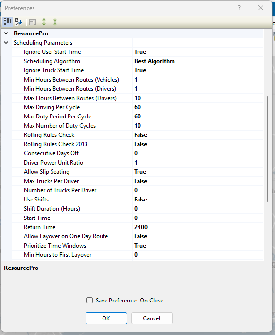 Figure 40. ResourcePro preferences
 -
Return to top of Preferences
- ROUTING
-
Preference options for automatic load building and optimization
Table 18. Routing preferences Routing Example Explanation ALGORITHM SETTINGS
Example
Explanation
Add Turn Time
True / False
Set to True to redispatch is selected in the Truck file. DR adds the specified turn time to the Route work time
Algorithm
Regular
Select the desired algorithm:
-
REGULAR — Normal two-way Routes
-
DOW — Day of Week, for fuel specific functions
-
INBOUND — Route from Stops back to depot, similar to a one-way inverted route
-
FARTHESTIN — Two-way Routes from the farthest Stop back to the depot
-
OUTBOUND — Farthest Stop is the last Stop, with return to the depot
5
Number of miles (size of box around Stops). Default is 1. When optimizing, the software constructs the smallest box that will contain all the Stops on a Route. Parameters affect the optimization process
Check In Cone
True / False
Set to True to force the software to select and group Stops in a geographical direction. (Not recommended for One-way routing)
Cone Angle
55
Angle of cone with the depot at the center. Default is 55
Depot Radius
10
Sets the size of the Radius (in miles) around the depot to determine which Stops can be loaded on the same Route out of cone. Default is 10
2
Determines how much weight to give cone expansion vs. distance from depot. Used by algorithm when deciding which Stop to load on a Route next. Lambda should never be less than 0.1 or greater than 2.0
Lambda Increments
.2
Incremental value added to LAMBDA, for each iteration, when constructing Routes. e.g., If Lambda is = .6, increments = .2, and iterations = 4, the software constructs Routes four times (iterations) in increments of .2, starting at .6 (e.g., .8, 1, 1.2)
Lambda Iterations
1
The number of times the software builds Routes using the Lambda Values. To find which value yields the lowest cost solution, run several Routes using 1 — 4
Max Redispatch Iterations
4
How the software determines the feasibility of redispatching a Route. E.g., If set to 4, the software creates up to 4 load passes to determine the best scenario
Max Wait Time
2
Maximum amount of time in hours a vehicle will be allowed to stay at a Stop
Max Dist Between Stops
250
Prevents Stops that are more than [X] miles apart from loading on the same Route
Optimize Stops After Loading
True / False
Set to True to move Stops between and within Routes to minimize cost
Optimize Trucks After Loading
True / False
Set to True to move loads from bigger to smaller Trucks to minimize cost if using various vehicle sizes in the Truck file
TW Gap For Buffers
1.75
If early and late buffer overlaps the gap between time windows, then they are adjusted to have the specified amount as gap between time windows. Value is entered as decimal miles
Load Backhaul Stop on Empty Truck
True / False
Set to True to load backhaul Stop on empty Trucks
Max Out of Route Miles For Backhaul
1000
Set max miles to consider for backhaul route. If Stop is farther than this, it will not be considered for backhaul
Max Percent Out of Route Miles for Backhaul
50
Set max percentage of Route miles, instead of distance, to consider for backhaul
Max Closest Stops
200
After the algorithm’s Route seeding process, it analyzes this number (closest Stops) to determine which are candidates to load next onto the same Route
Refuel Algorithm
Original
Select which algorithm to apply during routing:
-
Original — (Default) Uses the existing algorithm. Inserts refuel points based on Stop locations
-
Distance Based — Keeps track of Route capacity and adds refuel points only when capacity is available and 30% of work time is left in a Route. This option removes refuel points when not needed
Add Pre-Post time on redispatch
True / False
Set to True to add Pre-/Post-time on all legs. When False - adds only for the starting and ending terminal on the whole Route
Use Terminal as Refuel Point
True / False
Set to True to consider the terminal as a refuel point. If False - DR does not consider the terminal as a refuel point
Max Routes Per ID1
-1
Max number of Routes ID1 can have if multiple orders exist for the same ID1. Less than 1 will disable this feature. (See Split Stops)
General
Example
Explanation
Enable Start Time Column
True / False
Set to True and Start Time column is added to the Stop file. DR uses the Start Time listed in the Stop file as a Route dispatch time when initializing Routes. Use this function to require the need to edit individual Routes each time a change is needed to the actual Route start time
Allowing Logging
True / False
Set to True to set tracking mechanism for algorithm XML
Display Build Route file tab option
True / False
(For DRT users) Set to True to show Build Route file tab on New Route dialogue box
Distance Cache
1000000000
Max size of cache used for Distance file records
Drop Count
0
Affects the DropCost calculation for each Route by reducing the number of Stops on each Route that incurs on a DropCost
-
Route DropCost = (number of Stops on Route — Drop Count setting) x DropCost from the Truck file. If the number of Stops on a Route is less than the Drop Count setting, the Route’s DropCost is negative
Field used in Distance file
Lat/Long
Field, other than city, to use in Distance file (e.g., account, zip, lat/long)
Lock on Init and Load
Prevent addition
Options include: No lock, Prevent removal, Prevent addition, Prevent removal and addition, Prevent any changes. Read more about Init and Load and Lock Routes
Make Empty Trucks Unavailable after loading
True / False
Set to False to allow empty Trucks to be loaded during the Modify Load process
Maximum Stops Per Route
50
Set max number of Stops per Route. Affects Load algorithm, not Optimization
Mileage Adjustment
100
Percentage to adjust calculated mileage. Default is baseline 100. Ignored if distance entries are used
Minimum Time Between Stops (minutes)
0
Minimum time between Stops. Overrides drive time calculations if calculated time is less than this number
Apply Min Time Between Stops after directions
True / False
Set to True to automatically apply the Min Time Between Stops (Min)
Route Colors
Collection
Define colors for each Route
Route Line Width
Use the dropdown menu to select the width of the line displayed on the map (planned Routes on the map)
Color Empty Miles
Use the dropdown menu to select a color to apply on the map to portions of a Route performed by an empty vehicle
Scale Factor
0
Use to increase miles on a Route by a %. E.g., 1.1 = 110%
Secondary Route Identifier
TrkID
Secondary Identifier for a Route
Speed
50
Sets an average speed on a Route in MPH or KPH
Speed Adjustment (Drive Time)
95
Default is 100. % to increase or decrease Drive Time. Increase drive time = decreases vehicle speed and vice versa. E.g., 10% increase = 110 ; 10% decrease = 90
Use DirectRoute Drive Time
True / False
Set to True to use DR drive times instead of other installed Mileage System
0
Distance at which adjusted speed is implemented to account for traffic delays. Used in conjunction with Speed Adjustment and AM/PM Adj fields in the Stop file and/or Truck file. Required if the user is using AM/PM Speed Adjustments as found in either the Truck file or Stop file. Sets a radius around either the Truck originating point or the Stop location
Dispatch Date Offset
1
Number of days out from the date Routes begin dispatch/delivery
Consolidation Settings
Example
Explanation
Consolidate by ID1
True / False
Set to True to consolidate Stops by value in ID1
Consolidate by ID2
True / False
Set to True to consolidate Stops by value in ID2. Set to False if ID1 and Address are both set to False. An error message is generated if these settings do not align. Must be corrected to save/close the dialog box. Click on Cancel to exit without saving
Consolidate by Address
True / False
Set to True to consolidate Stops by address
Consolidate (Sum) Fixed Times
True / False
Set to True to consolidate Stops to the Fixed Time of first Stop in the group
Consolidate on Initialize
True / False
Set to True to consolidate Routes upon initialization
Static Splitting
Example
Explanation
Split Size
0
Sets minimum size of load to split. Set with split Stops TRUE and split orders FALSE
True / False
Set to True to allow splitting a Stop between Routes
Split Orders
True / False
Set to True to allow splitting an Order between Stops
Split Line Items
True / False
Set to True to allow splitting of line items between Stops
Quantity Field To Split
Pieces
Criteria used to calculate splits — Pieces or Retail. If None is selected, Static Splitting is disabled.
-
Pieces — Algorithm checks the sum of pieces
-
Retail — Algorithm checks the dollar value of the items
Dynamic Splitting
Example
Explanation
Split Stops While Loading
True / False
Set to True to split the load to ensure delivery of the product. If False, the remaining parameters for Dynamic Splitting are inconsequential
Split Orders
True / False
Set to True to enable splitting an order by line items rather than BY splitting the Stop. If set to False, the Stops must be split by full orders rather than line items
-
Adheres to the Splits-Min split size value
Split Line Items
True / False
Set to True to enable splitting the Stop at the line item level. Not valid for Stops that contain one order with one line item
Evaluate All Splitting Options
True / False
Set to True to enable splitting the Stop first by full orders, then by line items to fill the Truck to capacity. If set to False, the system stops evaluating when the split-by-full-order is successful even if the Truck is not at full capacity
-
The Split Orders parameter must be set to True
Max Splits Per Stop
1
Designates the maximum number of times a Stop can be split. This value is used when the MaxSplits field in the Stop file is empty. 1-2 splits is recommended
-
This field (Stop file) must be set to 1 or higher for the Stop to be considered for dynamic splitting (i.e., Each Stop contains at least one order, and each order contains at least one line item)
2000
Designates the minimum number of items that must be on an Order before it can be split. E.g., If the parameter is set to 2,000, an order with 1200 units cannot be split, but an order with 5000 units can be split several ways
Splits-Truck Full
0
Sets the Truck’s user-defined capacity limits for split consideration. The system loads Stops on a Route until it runs out of capacity (or runs out of allowed splitting options). See Splits-Min split size
Graph
Example
Explanation
Route Identifier 1
Route identifier from the Stop file
Route Identifier 2
Route identifier from the Stop file
Route Identifier 3
Route identifier from the Stop file
Route Identifier 4
Route identifier from the Stop file
Route Identifier 5
Route identifier from the Stop file
Route Identifier 6
Route identifier from the Stop file
Stop Capacity Adjustment
Example
Explanation
Capacity Field
Qty field to use for Stop capacity adjustment
Stop Adjustment
0
Qty to reduce capacity
Cross Dock & Relay Routes
Example
Explanation
Cross Dock Col Identifier
Column heading in Cross Dock file to identify cross dock location
Cross Dock file Path
Location of the Cross Dock file
Relay file Col Identifier
Column heading in the Truck file that identifies a Relay Route
Relay file Path (.xls, *.xlsx)
Location of the Relay Truck file
Password Protection
Example
Explanation
Enable
True / False
Set to True to enable password protection. Default is False
Password
True / False
Set to True to Add and Edit password
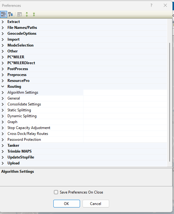 Figure 41. Routing preferences
 -
Return to top of Preferences
- Tanker
-
Load building preferences for compartments used with the Tanker Algorithm.
Table 19. Tanker Algorithm preferences Tanker Example Explanation Weight
Pieces/ Retail
Choose from Volume fields
Volume
Pieces/ Retail
Choose from Volume fields
Count
Pieces/ Retail
Choose from Volume fields
Tote file Name
C:\Program files\Appian\ DirectRoute\Data\ Tote.xls
Name and path of the Tote file. See the DirectRoute Data folder
Product Ratio file Name
C:\Program files\Appian\DirectRoute\Data\ Ratio.xls
Name and path of the Ratio file. See the DirectRoute Data folder
Use Tanker Algorithm for Product Assignment
True / False
Set to True to use tanker algorithm to ensure products loaded on Trucks are placed in designated compartments
Max Number of Totes Per Order
10
Max number of totes allowed on each order
Split Orders to Totes
True / False
Set to True to allow splitting of Orders into totes. If False - attempts to split the Order are only done on tanks
Split unloaded Stops and try loading
True / False
Set to True to split unloaded Stops and try loading
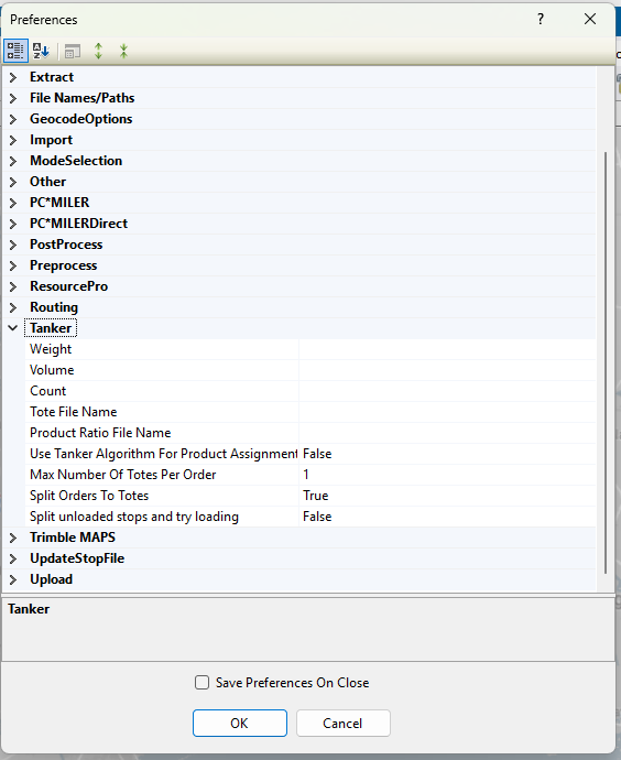 Figure 42. Tanker Algorithm preferences
Return to top of Preferences
- TRIMBLE MAPS
-
Route and Distance file options for use with Trimble Maps.
Table 20. Trimble Maps Trimble Maps Example Explanation Thread Count
8
Sets the number of threads to use during the distance generation process. Max threads = 16
-
Enter 0 to use all threads possible. This can slow down your computer during processing
Elevation
30000
Sets the elevation limit for routing. The unit of measure is based on Distance Options
-
If the Distance Option is set to Miles, elevation is entered as feet. If set to Kilometers, elevation is entered as meters
Route Across National Border
True / False
Set to True to allow Route to cross Canada and/or Mexico borders. If False - prevents border crossings, but may result in more miles
Route Type
Practical
Sets the routing type when getting directions. Options are: Practical, Shortest, or Fastest
Avoid Toll
Avoid
Determines if toll roads are acceptable. Options are: Avoid, Discourage, or Use
Hazardous Option
None
Indicates the directions hazard options
Vehicle Profiles
Collection
Vehicle profiles (sizes)
Distance Generation Mode
Pair (Matrix)
Option to change how Trimble MAPS generates distance entries
Default Vehicle Profile
Default vehicle profile to use. Select from one included in the Vehicle Profiles list
Use Historical Traffic Data
True / False
Set to True to use historical traffic data
Highway Only
True / False
Set to True to travel on highways and/or primary roads only
Use Content Tools
True / False
Data Version
Current
The PC*Miler version to use for Route calculations. Options are: PCM18 — Current
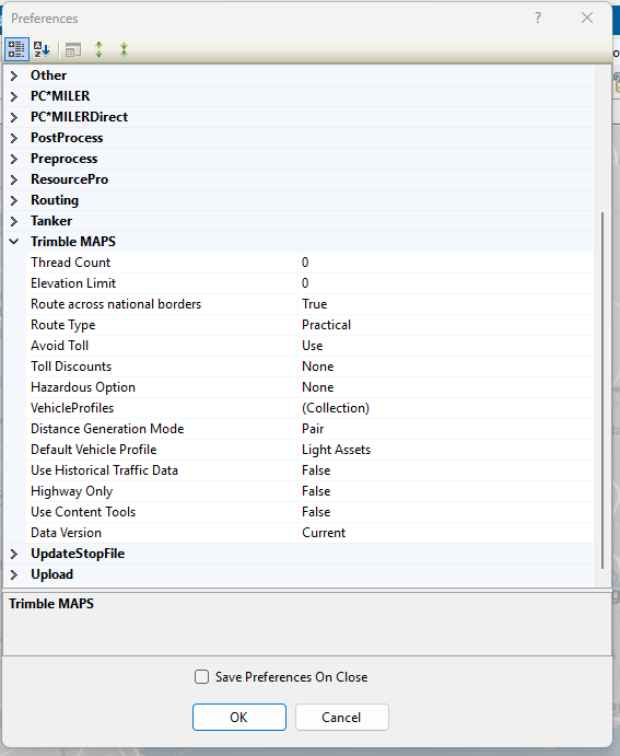
-
Return to top of Preferences
- UPDATESTOPFILE
-
Preferences that enable Stop file fields to automatically update during the Upload process
Table 21. Stop file fields and the Upload process Stop file Field Example Explanation Primary Identifier
ID1
Primary Stop file field
Secondary Identifier
ID2
Secondary Stop file field
Third Identifier
ID3
Tertiary Stop file field
Convert TW
True / False
Set to True to convert old style time windows to new
Return to top of Preferences
- UPLOAD
-
Upload preferences for exporting to an Order Management/ Host system.
Table 22. Export preferences Upload Example Explanation Upload Consolidated
True / False
If False (default), the UPL file lists each order separately. Does not consider if the consolidated Stops option is enabled (Load tab). If True, the orders/ Stops are passed in a consolidated format in the UPL file. Useful when you do not require each order to be listed separately
Upload Displayed Only
True / False
If True, file includes only the Routes displayed (locked) on the map. If False, the file includes all Routes for that routing session
Upload Header Record
True / False
If True, Places a Header row at top of the UPL file, with the number of routed orders
Upload Starting Terminal
True / False
If True, adds the beginning terminal/distribution center to the Upload file
Upload Ending Terminal
True / False
If True, adds the ending terminal/distribution center to the Upload file
Upload Date Format
MM/DD/YYYY
Choose date format to be used (e.g., MM/DD/YYYY)
Upload Day Format
Mo
Select how the day of the week is displayed (e.g., Monday, Mo, or Mon)
Upload Format file (*urp)
Select the file name and path of the URP format file to use. If added, the software only requests the file name during the upload process. Leave blank if using the XML file
Upload file Name
RTUPLOAD
The default file name is RTUPLOAD. Use the drop-down arrow to select another name. Can be changed after it is created
Upload file Path
(Blank)
Enter the location (path) where the file will be saved, if different from the current DirectRoute Data folder location
Upload file Type
*.UPL
Choose the file type to be produced (e.g., .upl, .xml, .txt, .cvs, or .xls)
Upload XML Version
5
Enter the XML version number — 2 or 5
Upload Sequence
True / False
If TRUE, the UPL displays orders by Route and Stop sequence numerically (as displayed in the Route Book)
OBC Upload
None
Allows choice of onboard computer system (XATA, PeopleNet, etc.) to Upload file format for OBC file
OBC Folder Path
Path to OBC file
OBC Upload file Name
RTUPLOAD
OBC Upload file name
Upload Time Format
Hmm
Choose time format. Options include: Hmm, HHmm, H:mm, HH:mm
V8 Compatible
True / False
Set to True to allow backwards compatibility with DR Version 8. If False, disables backwards compatibility.
Display Arrival and Departure Time on Consolidated Order
True / False
If True, displays the same arrival and depart time for consolidated orders on the same Stop
Display Miles on Consolidated Order
True / False
If True, displays the same miles for consolidated orders on the same Stop
Display Unload Time on Consolidated Order
True / False
If True, displays the same unload time for consolidated orders on same Stop
Ignore Terminal in XML Upload
True / False
If True, the upload ignores the terminal and only displays orders
Display Drive and Work Time on Consolidate
True / False
If True, displays drive and work time on consolidated orders
Abbreviate Rt Violation
True / False
If True, abbreviates Route violations
Display Total Distance on Consolidated Orders
True / False
If True, displays Route total distance on consolidated orders
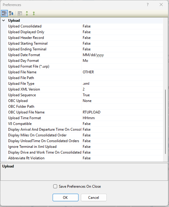 Figure 43. Upload preferences
Return to top of Preferences
Route Violations
Route violations are displayed in a few different Route Book locations — the Summary report on the Routes tab and the General drop down on the Route Info window.
Route violations happen when an action occurs outside the set parameters. DirectRoute uses the following:
| Abbreviation | Violation Name | Violation Description |
|---|---|---|
Window |
Time Window violation |
Delivery was made outside the set times established in the Stop file |
Drv Tm |
Drive Time violation |
Drive Time, set in the Truck file, was exceeded |
Wrk Tm |
Work Time violation |
Work Time, set in the Truck file, was exceeded |
Rtrn Tm |
Return Time violation |
The time allowed for a driver to return to the terminal, set in the Truck file, was exceeded |
Wt Tm |
Wait Time violation |
The vehicle exceeded the time allowed to wait at a Stop |
Cap |
Capacity violation |
Capacity limits, set in the Truck file, were exceeded |
EqCode |
EqCode violation |
Stop was loaded that does not meet the EqCodes for the Truck |
Seq |
Sequence Code violation |
The sequence code, entered in the Stop file, was not followed |
MaxDist |
Maximum distance violation |
The maximum distance allowed between Stops on a Route was not adhered to |
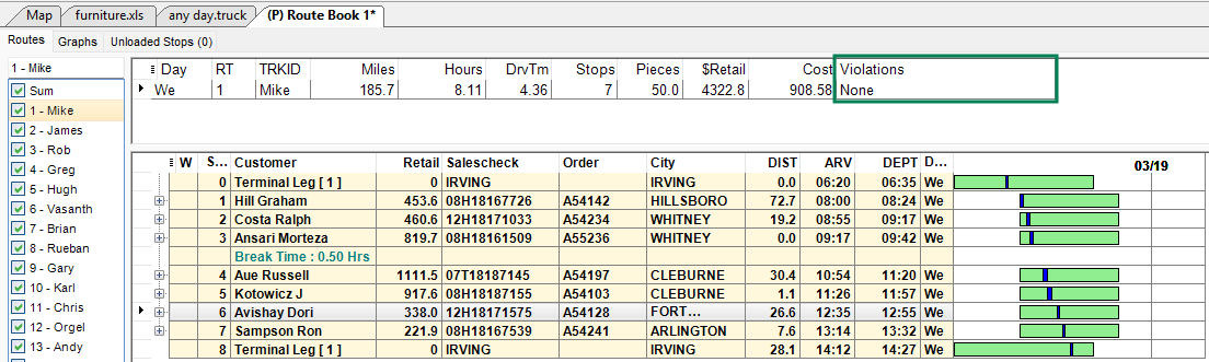
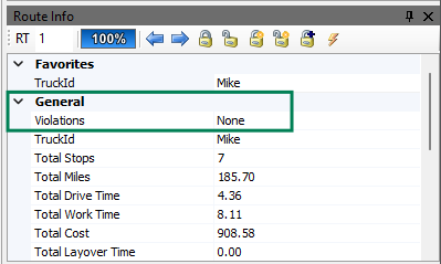
Check out this Violations video for more info.
Geocoding
Geocoding is the required process of finding associated geographic coordinates, expressed as latitude and longitude, from the address data provided in the Stop, Shipment, and Truck files. It enables the locations to be mapped and used to establish appropriate Routes. Review the Geocoding Setting section below for a description of the settings and functionality.
-
The application offers either full web service access to the Trimble Maps database, or an offline-mode service with PC*Miler 38-cached information available locally without an Internet connection.
-
All addresses in the Stop and Truck files must have a latitude/longitude attached for the routing process to work correctly.
-
Any records not geocoded are unloaded or reassigned by the algorithm, if used.
-
-
If the file already has the coordinates for each Stop, the Stops appear on the map when the file is opened in DirectRoute.
-
DirectRoute uses street addresses for the most accurate coordinates.
-
If the street address fails, the system falls back to City, State, and Zip to geocode the Stop and Truck records.
-
Ensure the addresses in each file are accurate before starting the geocoding process.
-
-
Once a record has been geocoded, it can be manually moved anywhere on the map using DirectRoute shortcuts; however, this updates the longitude and latitude in the Stop file.
-
Users can create a separate Custom Geocode file for hard-to-geocode locations.
-
Geocoding results can be validated with Google Maps API.
GEOCODING PREFERENCES & SETTINGS
Users have two mileage systems to choose from when geocoding records — Trimble Maps or PC*MilerDirect. The system is selected under Preferences > Other > Mileage System.
-
Trimble Maps is the default (and recommended) option and enables API connections that allow DirectRoute to obtain the most current information from PC*Miler.
-
This is the best option because the Geocoding process is completed using API calls.
-
The geocoding engine runs on the PC*Miler Single Search API. For additional details, click here.
-
-
PC*MilerDirect is the offline version of DirectRoute that does not connect to live information via APIs.
-
This option should be used in limited circumstances.
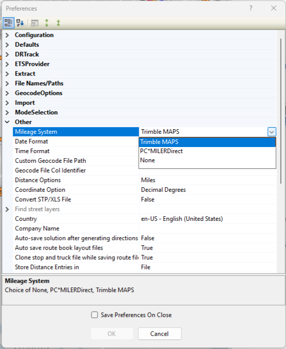 Figure 46. Mileage System preference
-
See figure below for the following:
-
Address Information — Contains the current address and row location for the record. Can be used to locate a singular record that requires editing.
-
Geocode Options — More than one option can be selected at a time.
*indicates options are available for both Trimble Maps and PCMilerDirect.-
Show Address Fields* — Check this box to see the address components like street and city in their own fields rather than the single text view used by the API.
-
Overwrite/ Update Provided Address* — Use this option to automatically update the address based on the results of the geocoding process. The Lat/ Long are always updated.
-
Skip Geocoded Stops or Trucks* — Enable this function if you wish to skip any records in a file that have already been geocoded. Helpful when new records have been added to an existing file. When checked, it does not update the Lat/ Long.
-
Color Code Symbols by Geocode Results* — Apply colors and symbols to visualize how records have been geocoded (Edit menu > Geocode > Color Code options).
-
Geocode by Name — (Trimble Maps only) Use this feature to geocode locations by business name when you may not have an address (does not require address when utilizing this feature).
-
Include Address2 in Query — (Trimble Maps only) Allow the second line of the address to be included in the geocoding process. Helpful when suite or building numbers or cross streets are needed.
-
Use Nearest Road Coordinates — (Trimble Maps only) Check this box when records may include remote or new locations that may not have an address yet, or hard to find locations. Geocodes nearest intersection.
-
Fallback to Zip — (PCMilerDirect Only) Use this option when other parts of the address are unknown or uncertain and the geocoding is dependent on the zip code.
-
-
Processing — Displays the file selected for geocoding, and the range of records within the file that are affected by the process.
-
Process Range — Starts the geocoding process.
-
-
Geocode Candidates — View the geocoding results for each record/ row. If a record was previously geocoded:
-
Eye icon — (top right corner of this section) Compare the previous geocoding results to the new geocoding results (highlighted yellow).
-
Accept Highlighted Result — Manually replace the address with the geocoded information.
-
Results — Displays the geocoding confidence level. Four levels available:
-
Level 1 — Very High — Exact and very close matches. Any potential match needs to be within 0.1 miles of each other. The top match is returned first and can only have very small differences between it and the input query (e.g., Street vs Road or N vs North).
-
Level 2 — Good — Close matches with a trust factor of 85% or greater. If the address is outside the range, the top match is within 500 address units of the input address, and other matches are all within 0.5 air miles of each other. (e.g., 100 Main Street is input, and the best match is 450-550 Main Street).
-
Level 3 — Uncertain — The match is uncertain, and the trust factor is 50% or greater.
-
Level 4 — Failed — A match has failed, and the trust factor is below 50%.
-
-
Address Error — Returns the reason for the confidence level when any part of the address differs (e.g., An address of 123 N Main Street is returned 123 North Main St. may have a confidence level of 1 and an AddressError type 6).
-
There are 18 Result type categories:
0 — Country
6 — Street
12 — POIType
1 — State
7 — RouteNumber
13 — CrossStreet
2 — County
8 — RouteAlpha
14 — LatLon
3 — City
9 — POI
15 — CustomPlace
4 — Zip
10 — POIStreet
16 — None
5 — SPLC
11 — FullPostCode
17 — TrimblePlaces
-
-
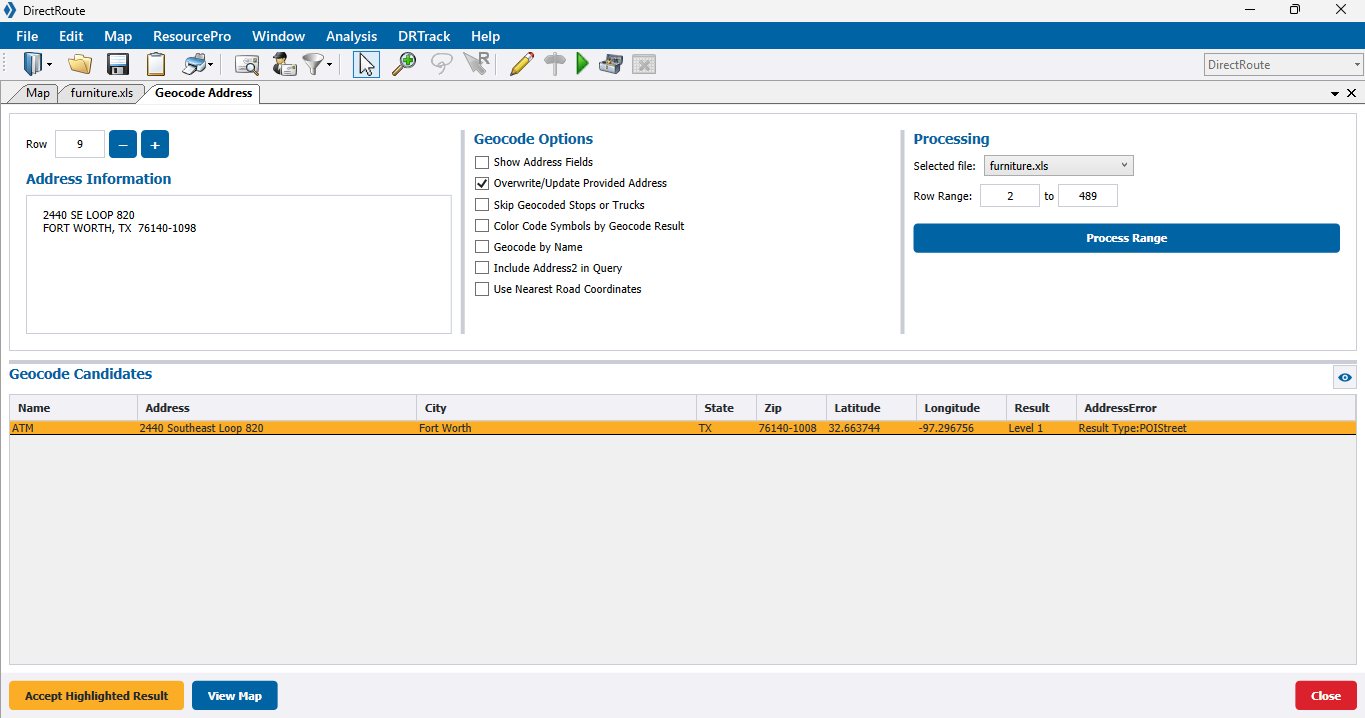
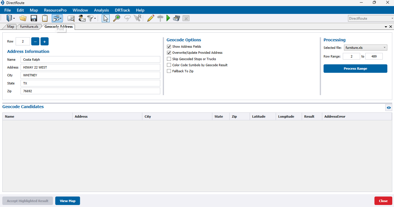
-
View Map — View the geocoded record on the map. The black dot indicates the original address. The green dot represents the new geocoded location.
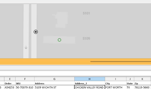 Figure 49. New geocoded results vs previous coordinates
CUSTOM GEOCODE FILE
The Custom Geocode file is an optional, separate file from the Stop or Master file. It is a spreadsheet containing special locations that are hard to geocode or cannot be geocoded normally (e.g., new housing developments, remote dockyards).
-
Only one Custom Geocode file is necessary.
-
The Custom Geocode file contains a user-defined SiteID and the longitude and latitude of the Stop.
-
The SiteID is a unique name or string used to:
-
Identify the longitude (e.g., -96.91080), and latitude, the positive number (e.g., 32.98247), of the specific location.
-
Allow DirectRoute to determine if a Stop in the Stop file is available for geocoding through the Custom Geocode file.
-
Allow many locations to be entered, even if not all the locations appear in each Stop file.
-
-
If the Stop file contains the coordinates for the SiteIDs, they can be copy/pasted into the Geocode file; otherwise, manually locate the coordinates for the file using the map.
-
DirectRoute first attempts to geocode the records by Address, ZIP+4, and then by the Custom Geocode file.
- GEOCODE FILE PREFERENCES
-
There are two Preference settings that require attention. Navigate following the path: File > Preferences > Other.
-
Custom Geocode File Path — Location of the Custom Geocode file.
-
Locate Geocode File Col Identifier — SiteID
-
The Stop file and the Custom Geocode file are required to have SiteID column headers.
-
-
GOOGLE MAPS API
Geocoding with Google Maps API is available to validate DirectRoute’s geocode results, or to obtain Canadian and Australian geocode results.
-
This is a limited alternative to DirectRoute’s built-in geocoding capabilities powered by Google.
-
Google Maps API uses an API Key, generated while using the Google APIs Console, to identify your application.
-
When the application calls an API enabled in this project, the application passes this key into all API requests as a key=API key parameter.
-
Use of this key doesn’t require any user action or consent, it doesn’t grant access to any account information, and it is not used for authorization.
-
-
Visit the Geocoding API for Work Web Services for instructions on creating a key and billing information.
-
If you already have a server key, you may use it.
-
-
Review required Preferences before starting (Preferences > Geocoding).
GOOGLE GEOCODING RESULTS
The results are displayed in the Stop file under the column heading Geo Result and Geocoding Results Info Box. Google may return several results when the address queries are ambiguous.
-
Rooftop — High accuracy. Indicates the result is precise down to the street address.
-
Range Interpolated — Same street. Indicates the result is an approximation, usually on a road, interpolated between two precise points, such as intersections.
-
Geometric Center — Same region. Indicates the result is the geometric center of a street (polyline) or region (polygon).
-
Approximate — Approximate. Indicates the result is approximate.
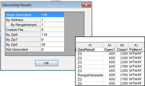 Figure 50. Google Geocode Results
For additional instructions, see the Geocoding section in the DirectRoute User Guide.
Advanced Routing Tools
DirectRoute Tools assist the user with creating and evaluating or customizing specific Routing scenarios. Click on the Quick View link for a brief comparison or click on the tool for a deep dive.
Quick View
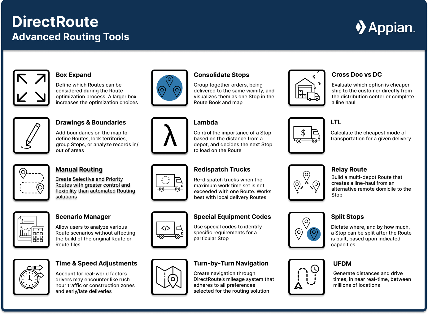
Box Expand
Box Expand is a parameter that defines which Routes are to be considered during Route optimization. Set these parameters under Preferences > Routing.
-
The Box Expand value is represented in miles and determines how far to expand the box around the stops.
-
The default is 1 mile.
-
Larger numbers increase the time it takes for the system to complete optimization.
-
-
During optimization, the software constructs the smallest box that contains all the Stops on a Route.
-
The logic does not consider moving Stops between Routes, unless their boxes intersect, even when the Routes are in the same vicinity.
-
Increase the parameter to allow the system to consider more Routes during optimization.
Example
Small box vs larger Box Expand values:
-
In the small box scenario, the boxes do not overlap, so optimization does not consider both Routes for Stop 4.
-
By increasing the parameter to 25, the boxes intersect allowing more moves to be evaluated.
-
The increased Box Expand value lengthens the amount of time the system takes to complete the optimization process but Stop 4 can be placed on the other Route saving mileage.
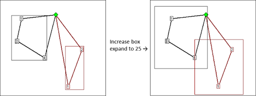 Figure 52. Box Expand - small box vs large box
To learn how to set and edit Box Values, see the DirectRoute User Guide.
Consolidated Stops
This feature allows users to group Stops by certain factors to help visualize the Stops and Orders easily on the map and in the Route Book. Apply settings under Preferences > Routing > Consolidate Settings.
| Consolidated Stops cannot be used with Split Stops functionality. |
Stops can be consolidated by one of the following options:
-
ID1 — All Stops that reference the customer’s account number can be consolidated.
-
ID2 — All Stops with the same customer alternative unique identifier can be consolidated.
-
An Error message is generated if Consolidated by ID2 is set to True and Consolidate by ID1 and Consolidate by Address are set to False.
-
-
Address — All Stops going to the same address can be consolidated even if the customer account numbers are different.
-
Consolidate (Sum) Fixed Times:
-
Set to True (Box is checked) — The fixed time for the consolidated Stop is equal to the sum of the fixed times for all the orders that are consolidated.
-
Set to False ( Box is unchecked) — The fixed time is equal to the fixed time of the first order in the consolidated group.
-
-
Consolidate on Initialize — DirectRoute consolidates Fixed Routes based on ID1, ID2, or Address, whichever option is enabled, during the Route building process.
-
Stops can be consolidated by customer (ID1/ ID2) or address when one of the following is also true:
-
Identical Time Windows
-
Identical EqCodes
-
Identical Size Restriction
-
Latitude/longitude is within three decimal places
-
-
-
When one or more Stops are consolidated, they appear as one Stop on a Route, designated with a
+symbol left of the sequence number. Click the symbol to see all the consolidated Stop details.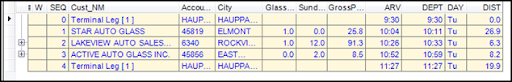 Figure 53. Consolidated Stops
Example
-
Two orders - a Deli order and a Hardware order - both with unique and separate order numbers, are to be delivered to the same Super Store location.
-
If the orders are consolidated, the Route Book shows both orders as Rt 3/ Stop 1.
-
If the orders are not consolidated, the Route Book shows the orders as separate Stops - Rt 3/ Stop 1 and Route 3 / Stop 2.
Cross Dock vs DC
The Cross Dock vs DC (Distribution Center) tool allows users to evaluate customer service areas, where multiple methods for distribution exist, and determine the best network design solution based on cost. E.g., Is it cheaper to ship / service the customer directly from the distribution center or complete a line haul to a local cross-dock or warehouse for final delivery. The generated solution can then be fed to DirectRoute to determine the best Route and Stop sequence.
-
The algorithm does not evaluate the feasibility of the Route, driver work rules, or customer-specific time windows and service times.
-
The DC is the main hub or manufacturing location for all end-user products. There should only be one DC for the solution.
-
The Cross Dock vs DC solution uses the Stop and Truck files (Distance file is optional). Apply additional settings under Preferences > Configuration:
Stop file:
-
No required Stop User fields.
-
Customer list — Drives the demand for the evaluation.
-
Volume displayed — Can be a daily volume or an average weekly amount.
Truck file:
-
Mileage Cost (MiCost) — feeds the cost evaluation
-
Cost from DC = (Stem Mileage of each stop from DC x 2) x Mileage Cost x (TTL Stop Volume / TTL DC Truck Capacity).
-
Cost from Crossdock = (Stem Mileage from Cross-Dock x 2) x Mileage Cost x (TTL Stop volume / TTL Cross-Dock Truck Capacity) + (DC to Crossdock Mileage x 2) x Mileage Cost x (TTL Stop Volume / TTL Linehaul Truck Capacity).
-
Multiplying the Stem Mileage x 2 accounts for round trip mileage. Two columns are inserted in the Stop file for DCCost and CDCost.
-
-
Must have the City name.
-
Must have the TruckType Truck User field.
-
There are three different Truck types/ scenarios tied to the TruckType:
-
Blank field = Trucks the main distribution center has for delivery to their local customers.
-
LH = Trucks available for Line Haul deliveries (e.g., warehouse to warehouse).
-
CD = Trucks available for Cross Dock deliveries (e.g., Cross Dock to end customer).
-
-
The main DC utilizes all three TruckTypes.
-
The Cross Dock facilities utilize CD TruckTypes only.
-
The number of Trucks entered in the Truck file represents the typical amount of Trucks needed to satisfy the current workload.
-
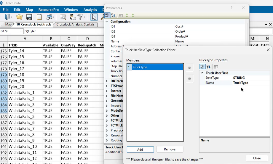
Drawings & Boundaries
Drawings enable boundary visualization during the Route building and editing process. Boundaries allow users to use those colors/ patterns to denote zones for statistical analysis or special route building scenarios.
- DRAWINGS
-
Users can add drawings to DirectRoute two different ways. Learn how to create and upload Drawing files in the DirectRoute User Guide.
-
Upload a drawing file.
-
Draw directly on the map using application tools.
-
Contains several line options, shapes, shading, and color choices. Hover over the icons to discover their actions.
-
Can be enabled in DirectRoute with/ without any files open.
-
Can be saved, printed, edited, and reused.
-
Open the saved drawing file before activating the toolbar.
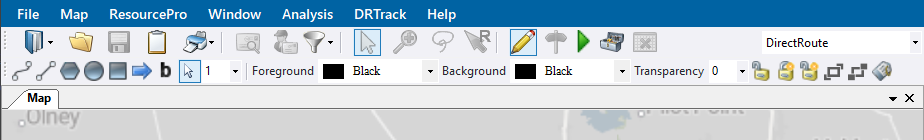 Figure 55. Drawing Tools Toolbar
 -
-
Drawing Tools enables users to:
-
Draw boundaries directly on the map to define Routes, lock territories, or group Stops.
-
Add text boxes/ labels to areas on the map.
-
Assign vehicles and/or driver.
-
View statistical analysis for records within or outside the boundary.
-
- DRAWING TOOLS
-
-
Gold Padlock — Locks Territories on the map, preventing them from moving during the planning phase, but enables them for editing.
-
Hover over the icon to open the info box and determine/ change locked status:
-
Lock Selected Shape
-
Lock All Shapes
-
Unlock All Shapes
-
-
-
Text Tool — Places a text box on the map for labeling territories, areas, or regions.
-
Hide Labels — Hides text boxes and labels while working in the Drawing file.
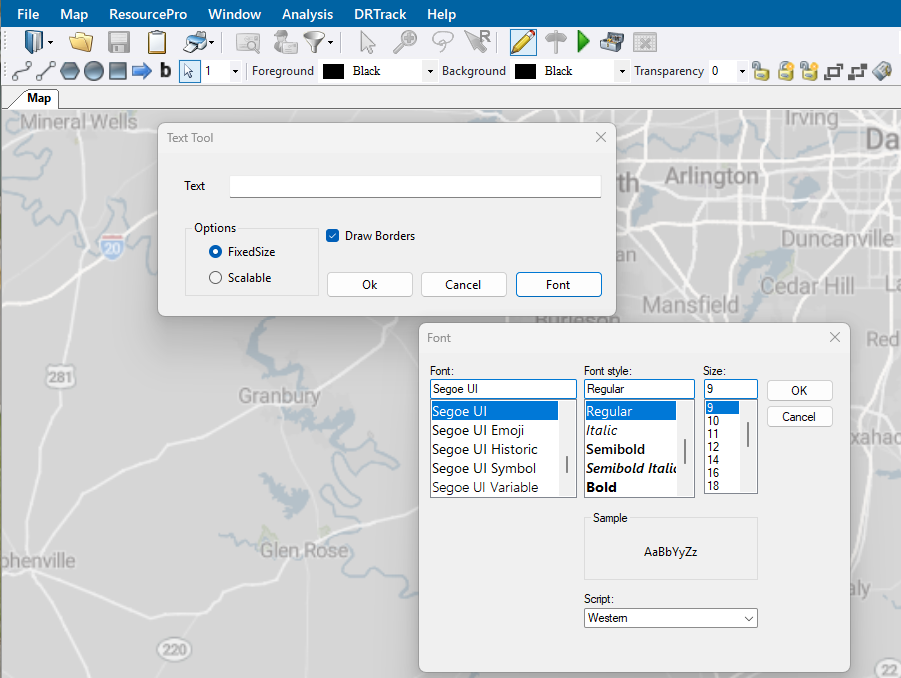 Figure 56. Text Tool window with font selection
-
-
Line Tools — Draw boundaries, add borders around a group of Stops or Routes, or define Routes or territories with segment lines and arrows.
-
Polyline — Enables the drawing of multiple connecting line segments on the map.
-
As each line segment is drawn, the status bar shows the length of that segment as well as the total distance of the polyline.
-
Useful for displaying cumulative distances between areas on the map.
-
-
Line — Enables the drawing of a single line segment - useful for displaying the distance between to Stops on the map.
-
Arrow — Enables arrows on the map to mark a spot with a triangle or point to an object.
-
The distance of the arrow’s line is displayed in the status bar.
-
-
-
Boundary Tools — Add boundaries directly on the map with an enclosed shape - circle, rectangle, polygon - with various patterns and colors.
-
Denote a special attribute about an area using colors and patterns.
-
Calculate the statistics of records within an area.
-
Select records within a boundary for analysis.
-
Circle — Enables the drawing of a circle on the map. The circle can be drawn to have a specific radius (which can be displayed in the status bar in the bottom left of the map).
-
Rectangle — Enables the drawing of a rectangle on the map. The width and length of the rectangle are shown in the status bar.
-
Polygon — Enables drawing an editable boundary of any shape on the map.
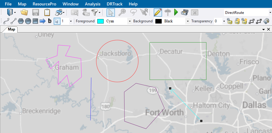 Figure 57. Line and Boundary Tools with color selections
-
-
-
- BOUNDARIES
-
Boundaries are used to analyze the information in a data table and view the results on the map. Before using this functionality, ensure required boundaries are drawn (with the tools above) and the required file is open.
The three main functions used with boundaries include:
-
Template Overlay — This tool serves two basic purposes:
-
Denote a special attribute about an area with the use of colors and patterns (e.g., add an overlay to view the Routes within a sales territory).
-
Paste data into records that exist inside / outside the boundary (e.g., change the symbols of the customers that fall within that sales territory).
Select how the template actions work with Overlay and While Overlaying options:
-
Overlay — Uses the Stop file data in the Selected column (True/ False) to direct the Template actions. This data can be adjusted in both the Stop file and the Template window.
-
Ignore Selection Status — Select Stops within the boundary regardless of their Selected status in the Stop file (e.g., changes the color of all Stops no matter their Selected status of True of False).
-
Selected Records only — Filters the records identified as Selected = True (e.g., Only changes the color of the Stops that are Selected).
-
Unselected Records only — Filters the records identified as Selected = False (e.g., Only changes the color of the Stops that are unselected).
-
-
While Overlaying —
-
Don’t change selection status — Prevents the actions from changing the response in the Stop file’s Selected column (e.g., from True to False)
-
Select records — Change the records to Selected status (True)
-
Unselect records — Change the records to Unselected status (False)
-
Toggle selection status — Switch between Selected and Unselected Stops in the created boundary to find Stops faster on the map
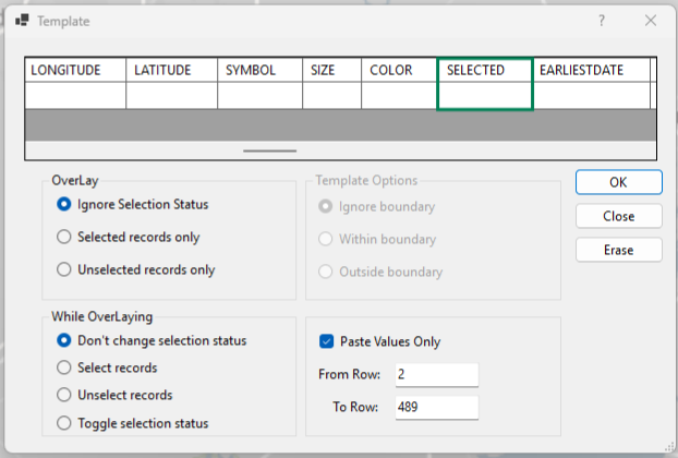 Figure 58. Template options
-
-
-
Statistics Calculation — Calculate the statistics of records within an area. Includes In Boundary and Out Boundary results.
-
Use the Drawing tools to alter boundaries and recalculate.
-
Use the F8 key to display the data.
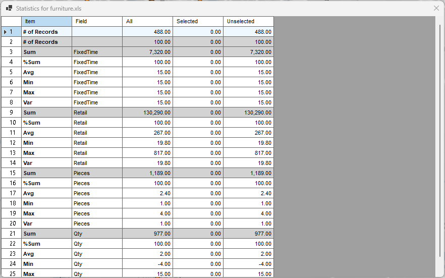 Figure 59. Template statistics
-
-
Build to Value — Color-codes locations based upon the geographical area and a volume criterion. It is helpful in the following activities:
-
Building a Skeletal Route based upon area and delivery quantities.
-
Building a Sales territory based upon area and sales quantities.
-
Analyzing Site locations (which customers can be serviced based upon warehouse capacity).
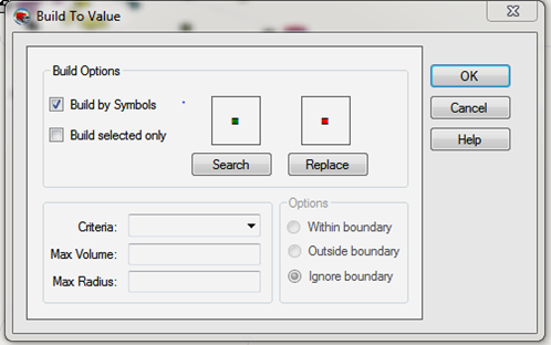 Figure 60. Build to Value window
-
-
Lambda
Lambda is a variable factor that controls the weight of a potential Stop based on its distance from a depot. The routing algorithm uses Lambda to decide the next Stop to load on a Route. Apply settings under Preferences > Routing > Algorithm Settings.
-
Lambda values range from .1 — 2 depending on the density of the stops in your delivery area.
-
A Lambda value of 0 gives no weight to the distance.
-
The default setting for Lambda is 2.
-
High density Routes (many Stops) require a lower Lambda value.
-
Routes with high Stop counts (dense routes) - lower the Lambda value and run tests to determine the right number (1-1.5).
-
Setting a Lambda value of less than 2 causes DR to build tighter Routes (narrower cones) but may result in an increase in miles.
-
There are three values to set. Experiment with the value to decide which setting is best for your routing environment:
-
Lambda Setting — Specifies the initial Lambda value, or the value of Lambda to use for running Iteration 1.
-
Lambda Iterations — Number of times to calculate Routes using increments.
-
Once the best settings are determined, set the Iterations to 1 to prevent the Route from running several times to determine the best option.
-
When using Redispatch, Iteration 1 is recommended.
-
If you wish to cancel the Route loading process, user must cancel each of the iterations. When one is canceled, the next Route begins.
-
-
Lambda Increments — Value used to increase Lambda while calculating Routes. Allows several attempts to create a routing solution that yields the lowest cost.
- Example 1
-
Scenario:
-
Lambda setting = 0.6
-
Iterations = 4
-
Lambda Increments = 0.2
DR constructs Routes starting at the Lambda Value of 0.6 and increases each time by 0.2 (0.6, 0.8, 1.0, and 1.2). It will attempt 4 times then display the solution that yields the lowest cost.
-
- Example 2
-
Scenario:
-
The depot is represented by the green diamond, and the three red squares are Stops to be routed.
-
Each Stop has a volume equal to one half of a vehicle’s capacity, requiring two vehicles to service the three Stops.
-
Lambda value is set to 0.
-
The algorithm typically loads the farthest Stop from the depot first (Stop A).
Decision:
Which Stop to pick up next (either B or C) is based on a combination of mileage added to the Route and the distance the Stop is from the depot multiplied by the Lambda factor.
-
The Stop selected next is Stop C because it adds almost no additional mileage to a Route already going to Stop A.
-
This vehicle is now full and requires the second Route to service Stop B.
-
This solution has higher miles than a solution that pairs Stops A and B, but the Lambda value is 0 and gives no weight to distance.
 Figure 61. Example 2 Stops and Depot
-
-
- Example 3
-
High vs Low Lambda values:
-
Each scenario has three Routes.
-
High Lambda is 3% fewer miles because they are only running two trucks to the outer perimeter Stops (red and black Routes) versus the three Routes using low Lambda.
-
The higher the value, the more weight placed on distance.
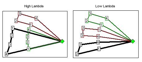 Figure 62. Example 3 High vs Low Lambda values
-
To learn how to set Lambda values, see the DirectRoute User Guide.
LTL Costs
Use DirectRoute to calculate the cheapest mode of transportation for a given delivery. On small orders, it may be cost-effective to hire a third party for shipping vs using your own fleet. Apply defaults using settings under Preferences > ModeSelection.
Example
Should we deliver an order or hire someone else for shipping?
To answer this question, provide the algorithm with the costs for a particular order to be shipped with an LTLCost field in the Stop file and settings in Preferences. The LTL Cost is the flat rate, in dollars, for delivering an item via a third-party service.
-
LTLCost field must be entered manually in the Stop file without spaces to work.
-
The Algorithm setting for Optimize Stops After Loading must be set to False, although manual optimization is allowed.
-
The DirectRoute evaluates the MiCost (mileage cost), HrCost (hourly cost), and the LTL Costs fields in the Stop file (among others) to compare costs.
-
LTLCost is viewable in the Unloaded Stops tab of the Route Book. You cannot drag it to add to the Routes tab in the Route Book as you can with other Stop User fields.
-
Use the Stop file with the LTLCost fields during Route building to assist with the Stop Loading process. If a Stop is not loaded and the violation is LTLCost, then the algorithm determines it is cheaper to ship the order than it is to deliver it.
Manual Routing
DirectRoute provides two distinct manual Routes to choose from: Priority and Selective. Both options allow orders (Stops) to be imported directly from DRTrack™ to create these Routes. Access under the File Menu > New. There are several other ways to manually create Routes, the lasso may be the simplest. Find instructions in the DirectRoute User Guide.
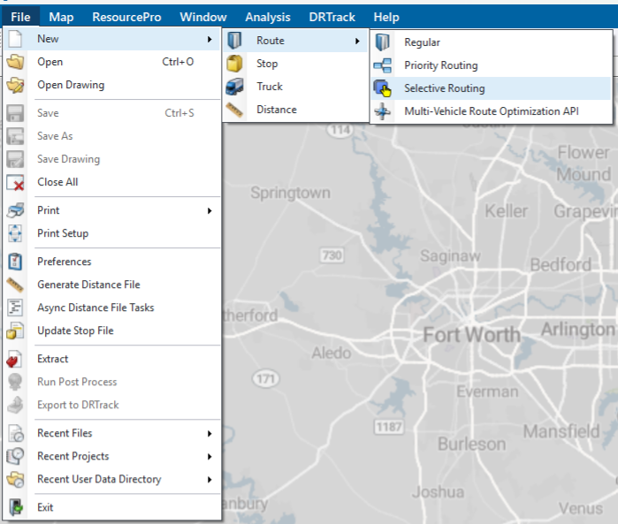
PRIORITY ROUTES
Priority Routes are created with a manual Route building tool, alongside DRTrack™, that provides greater control and flexibility, and the ability to edit Routes, in the build process, with a simple format.
-
Offers Route building options not regularly available for selection.
-
Provides valuable Stop information in a grid view.
-
Displays a preview of the routing solution before committing to changes.
-
Statistics and violations are displayed for each Route and Truck on the right side of the Route grid, and update automatically as changes are made.
-
Built Routes and Route statistics also appear in the Route Book. Truck statistics appear under the Truck icon.
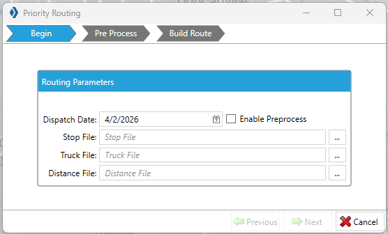 Figure 64. Priority Routing
 -
SELECTIVE ROUTES
Selective Routes are created with a manual Route building tool that includes an order filter to provide flexible controls for Stop and vehicle selection during the Route building process. Ensure the Stop User fields and Order Criteria fields are up-to-date before using.
-
Uses a Stop User field to filter orders to Route.
-
Apply load adjustments to vehicles using a sliding meter — vehicle Capacities (Volumes), Work Time, Target Time, and Max Drive Time.
-
Modify Selective Routes and any unloaded Stops in the Route Book. View on the map:
-
Red = unloaded
-
Green = Routed
-
Re-dispatch Trucks
Redispatch is a feature that is used with local delivery Routes when the maximum work time set for the Truck is not exceeded with one Route. The short delivery time allows the Truck to be dispatched on multiple Route legs during a single day.
-
If the Redispatch column in the Truck file is set to True, the Truck is available for Re-dispatch.
-
This field is ignored if the Oneway column is also set to True.
-
-
Redispatch Minimum Time — The minimum amount of work time remaining (in hours) before considering Redispatching.
-
Redispatch Turnaround Time — The amount of time it takes to reload the Truck after it has returned to the depot (in minutes).
-
All dialogs that require a Route number also require a leg number.
-
Information is entered into the Route field, separated by a comma (e.g., 1,2 = Route 1 / Leg 2).
-
If the leg number is omitted, the system assumes it is Leg 1.
-
-
Example
-
A distributor delivers to local customers in full truckload quantities.
-
One entire Route only takes a couple of hours to deliver and return to the depot.
-
This allows the Truck to reload and deliver another Stop.
-
This process is repeated until the Truck is out of work time.
-
The max work time is set to 10 hours, and the minimum time is set to 2 hours.
-
Redispatching ceases when the Route has 8 or more hours of run time (10 hrs - 2 hrs).
-
Set the minimum time to zero, and it assumes that another driver is taking the next leg of a Route. Work time statistics are reset to zero.
-
Check out this Redispatch video for more info.
Relay Route
The Relay Route allows the shipper to simulate warehouses where there may only be a drop and hook trailer yard. It is a multi-depot Route that creates a line-haul from an alternative warehouse, dock, yard, or domicile to the actual warehouse (referred to as the remote domicile). The Routes are started from the remote domicile to the delivery point.
-
Create a Relay by Destination or by Truck.
-
Relay by destination — Creates a line haul from the remote domicile to the main depot (destination).
-
Relay by Truck — Creates a line haul from a truck dispatch location that is not the remote domicile or depot.
-
-
The Truck file should contain entries specifically for Relay Routes.
-
It is helpful to name Trucks, used with Relay Routes, with unique names to easily identify them with Relays.
-
Each location of the relay has its own entry.
-
Each truck should have the City column populated and the record geocoded.
-
Ensure the values for Edate/Ldate/EarlyStart/LateFinish allow enough time for the Relay to be completed.
Scenario Manager
The Scenario Manager tool allows users to analyze various Route scenarios without affecting the build of the original Route and files. If the scenario results are more favorable, they can be saved and applied to a new Route. Use it to answer questions like:
What is the impact if worktime is reduced from 9 to 8 hours?
Is there a cost benefit in expanding delivery windows by 30 minutes?
If service time is reduced by 5%, how much savings would be generated?
The tool:
-
Uses temporary changes to Route Field and Stop Field values within the Route files to determine what effects the changes would have on the overall Route solution.
-
Displays the results at the bottom of the Scenario Manager box, including the original Route values before adjustment (BaseResult), the new values (ScenarioName), and the change value (+more or –less).
-
-
Saves the original Route files unchanged and creates/saves duplicate files with the changes applied. The new files contain the scenario name as an extension to the original file name (e.g., original file name = Phx1502, new file name = Phx1502-Mileage Cost).
-
Ensure the desired Route file is opened in the Route Book to run the saved scenario.
-
-
Optimize after Loading — Scenario Manager applies Optimization if set to TRUE in Preferences > Routing > Algorithm > Optimize Stops After Loading.
-
Time Windows / Buffers — Scenario Manager has additional Time Windows and Buffers parameter options. Set these parameters using the Dropdown and More menu (three lines) within the tool.
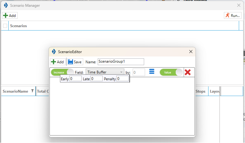 Figure 65. Time Buffers
-
Time Windows Parameters:
-
Only If/ Always — Sets when the Time Window should be increased or decreased.
-
Gap — Refers to the number of hours the Time Window is open.
-
-
Buffers Parameters:
-
Early/ Late — The number of hours to apply to the Open (Early) and Close (Late) Time Windows.
-
Penalty — The dollar amount to apply as a penalty when/if the buffer is applied.
-
-
Example 1
Scenario: Increase Time window
-
A Route contains a mix of Time Windows with open periods of 4 and 6 hours.
-
What is the impact when all the open periods are set to 6 hours?
-
Increase Time Window value by 2.
-
Set to Only If and enter a Gap value of 6.
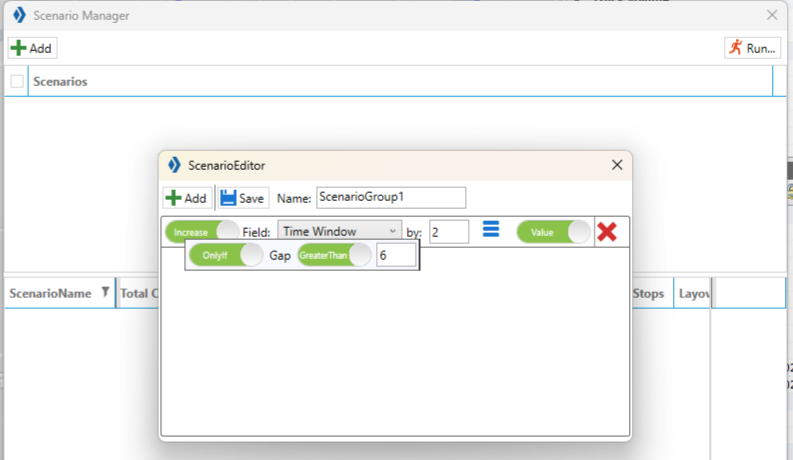 Figure 66. Scenario Manager Time Windows
Example 2
Scenario: Increase Max Drive Time and Max Work Time
-
The Max Drive Time on the current route is 6 hrs.
-
The Max Work Time is 7 hrs.
-
Increase the Max Drive Time by 2 hrs. and our Max Work Time by 2.5 hrs.
-
The results indicate the total cost decreased (by $1583.31), the Distance decreased (by 277.87), and Elapsed Time decreased (by 5.47).
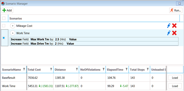 Figure 67. Scenario Manager Results and changes
Special Equipment Codes
Special Equipment codes are entered into the Stop file to identify specific requirements for a particular Stop. They are helpful for mixed fleets with unique equipment or deliveries that require a specialty truck.
-
Use multiple codes for one Stop (separate by a dash)
Below are seven special equipment codes to use with these routing scenarios. Click on their links to learn more:
Type |
Format |
Length |
Truck File |
Alphanumeric |
Any |
Yes |
|
BH |
2 characters |
No |
|
!1- to !9 |
2 characters |
No |
|
00 to 99 |
2 characters |
No |
|
1.01 or 25.01 |
4-6 characters |
No |
|
@Alphanumeric |
Any |
Yes |
|
^Alphanumeric |
Any |
No |
|
&Alphanumeric |
Any |
No |
|
#AA1/#AA2 to #ZZ1/#ZZ2 |
4 characters |
No |
EQUIPMENT
Equipment codes (EQ) identify specific equipment requirements for a Stop.
-
User-defined, alphanumeric characters (e.g., LG = Lift gate, FB = Flatbed)
-
One or more Trucks, in the Truck file, must be designated with the same code(s) to identify its compatibility with the coded Stops (i.e., If a Stop has three codes, there must be a Truck with the same three codes).
-
Coded Trucks can load Stops without codes.
-
Coded Stops require a coded Truck.
-
-
Trucks with Eq codes should be added to the bottom of the Truck file to ensure they are reserved for Stops with codes.
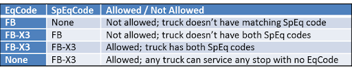 Figure 68. SpEq Codes in the Truck file
BACKHAULS
A Back Haul (BH) is a Stop for a pick-up rather than a delivery. It requires an empty truck that can be returned to the terminal, so it is the last leg of the Route. It should not be confused with a regular pick-up-to-depot delivery that can happen anywhere within the Route.
-
Identified in the Stop file with an EqCode of BH.
-
DirectRoute places BH Stops at the end of the Route to ensure the truck is empty.
-
There does not have to be a corresponding BH code in the Truck file.
-
Stops coded as Back Hauls can be loaded on any Truck unless the Stop has additional coded constraints.
-
Back Hauls are shown in the Route Book with a negative capacity.
PRIORITY
Priority Codes allow the user to influence the order in which Stops are loaded in the build phase of a Routing solution. A Priority Code does not ensure that a Stop is the first on a Route, only that it gets loaded before all others without a Priority Code. When no priority codes are identified, DirectRoute loads the farthest un-routed Stop, on an empty vehicle, first then loads additional Stops within the same vicinity.
-
Identified in the Stop file with an EQ code of an exclamation symbol (!) followed by a sequence number between 1 and 9.
-
1 is used to indicate the highest priority and 9 the lowest.
-
-
There does not have to be a corresponding BH code in the Truck file.
-
Stops coded as Back Hauls can be loaded on any Truck unless the Stop has additional coded constraints.
-
To influence the order of the Stops on a Route, see Sequence Codes.
SEQUENCE
Sequence Codes force DirectRoute to build the Route using the delivery sequence input for each Stop.
-
Identified in the Stop file with an EQ code consisting of a 2-digit number (00-99).
-
The lowest sequence number has the highest priority and is loaded before Stops with a higher sequence number.
-
-
If you use sequence codes, every Stop in the Route must have a code.
-
Blank cells in the EqCode field are given a null value (00) which gives them top priority and forces a first delivery.
-
-
Any numerical code (without alpha characters), entered in the EqCode field, is assumed to be a Seq Code.
-
Always test values to ensure they do not have an adverse effect on operations.
Example
The following table represents coded stops in the Stop File.
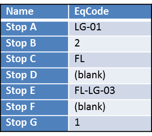 Figure 69. Stop file with EQ codes
-
Stop A — Requires a 1st delivery Stop (Seq Code 01) and a lift gate (EqCode LG)
-
Stop B — Requires a 2nd delivery Stop
-
Stop C — Requires a forklift, but no sequence code provided
-
Stop D — No requirements and no sequence code provided
-
Stop E — Requires a forklift, a lift gate, and a 3rd delivery Stop
-
Stop F — No requirements and no sequence code provided
-
Stop G — Requires a 1st delivery Stop
Based on the file:
-
Stops A and G should be delivered first based on their sequence numbers
-
Stop B should be the second Stop
-
Stop E is the third Stop
-
Stops C, D, and F are not given a sequence code, so a default null value forces their deliveries first
-
To avoid a mix-up in Stop sequence, enter a sequence code for C, D, and F (Starting at 4)
-
SEQUENCE PREFERENCE
A Sequence Preference Code (SpEq Code) is the dollar amount assigned to a coded Stop. When DirectRoute builds and optimizes Routes, it calculates the cost of the Route (referencing the cost fields in the Truck file)
-
Identified, in the Truck file, using an EqCode containing numerical characters that represent the dollar amount. A decimal is accepted (e.g., RF-3.25).
-
If a SpEq Code is used in the Stop file, the system will add the additional cost to the Routes.
-
The earlier in the Route the Stop is sequenced, the lower the calculated cost.
-
Formula = the assigned value for the preference code * (the Stop Seq Code number - 1)
-
Example
If a Stop is assigned a Sequence Preference code of 3.25 and a Sequence Code of 5, then the Formula is $3.25 * (5-1) = $13.00
TERRITORY
Territory Codes force Routes to remain within an identified area.
-
Identified by using the @ symbol with two alphanumeric characters (ex. @A2).
-
Codes are entered in both the Stop and Truck file in the EqCode and SpEq fields.
-
Stops with a Territory code can be loaded on any Truck unless the Stop has additional coded constraints.
-
Generally, when a Territory code is placed on one Stop, they are placed on every Stop and all Trucks.
-
Territories can be as small as one truck, or have multiple Routes assigned.
-
-
If drivers are assigned to a specified territory that must remain within the territory lines, add Territory codes in the Truck file to restrict the Stops that can be loaded on the Truck.
-
The difference between a Territory Code and a normal EqCode:
-
Territory codes on a Truck must be a subset of the codes on a Stop.
-
Normal EqCodes on a Stop must be a subset of the codes on the Truck.
-
Example
The following shows territory codes in the Truck file. ** Customer [X] can be serviced by drivers assigned to Territories 1, 2, or 3, but cannot be serviced by driver of Territory 4.
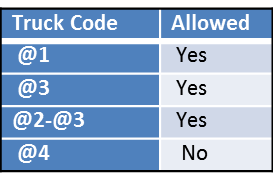
EXCLUSION
Exclusion Codes (Ex code) are used to specify that two or more Stops cannot be loaded on the same vehicle. These are hard rules, meaning the Load algorithm must always exclude these Stops. The system leaves a Stop unloaded before adding it onto a Route with a Stop that has the same Exclusion code.
-
Identified, in the Stop file, using an EQ code with the
^symbol plus two alphanumeric characters (e.g., ^A2). -
Does not require a corresponding Exclusion code in the Truck file.
-
Stops with the same Ex Code will not be loaded on the same vehicle.
-
Stops with an Exclusion code can be loaded on any truck unless the Stop has additional coded constraints.
Example
-
A beverage distributor delivers to a customer who receives three deliveries per week.
-
The Stop file represents deliveries for a typical week.
-
Each Stop in the Stop file represents one delivery.
-
A customer who receives three deliveries in the week has three records in the Stop file.
-
-
An EX code is used to ensure the deliveries are spaced out three times that week rather than loaded on the same vehicle for delivery on the same day/ time.
INCLUSION
Inclusion Codes are used when multiple orders are delivered to the same area to ensure they are placed on the Truck that regularly runs the Route. These are soft rules, meaning these Stops are placed on the same Truck unless the Load algorithm runs into another hard rule such as MaxWorkTm, Capacity, or another EQCode. It can break up Stops with the same Inclusion Code and place them on another Route.
-
Identified, in the Stop file, using an EQ Code with the
&symbol. -
Stops with an Inclusion code can be loaded on any truck unless the Stop has additional coded constraints.
-
There does not have to be a corresponding Inclusion code in the Truck file.
Example
-
A clothing distributor delivers multiple orders to the same outlet mall and wants to ensure all the deliveries are on the same truck.
-
An Equipment Code of &OutletMall ensures all these deliveries are placed onto the same Route.
ORIGIN-DESTINATION
Origin-Destination Pair (OD) codes are used to force DirectRoute to load a pair of Stops on the same Route, in proper order, as an exception to the standard Depot-to-Stop routing. If one Stop lists an OD Pairs code, there must be another Stop at some point in the Route with a matching code.
-
Identified by using a pair of codes with the
#symbol, a two-digit alphanumeric, and a sequence number (e.g., #AA1 and #AA2).-
The lower sequenced number in the pair (#AA1) represents the Origin Stop, and the higher sequenced number (#AA2) is the Destination Stop.
-
The Stop coded with the lowest number is loaded first.
-
The first Stop of an OD pair is displayed in the Route Book as a negative number to represent the Stop as a pickup.
-
-
OD Pairs should account for less than 20% of the total Stops in one routing solution.
Example
-
Using the pair #AA1 and #AA2, #AA1 loads first.
-
DirectRoute checks the capacity of the vehicle against the volume to be picked up to ensure there is enough space on the vehicle, when it leaves the terminal, to pick up the Origin Stop.
-
Vehicle capacity is set at 17,000 pounds.
-
14,000 pounds are loaded at the terminal for various Stops on the Route.
-
An additional 2,200 pounds must be picked up at another location before all deliveries can be made.
This is a valid OD Pair
The Stop with the matching OD Pairs code need only be loaded after the pick-up. The remainder of the Route is built in the usual manner, with appropriate consideration given to other equipment or sequence codes.
Split Stops
Splitting a Stop can improve capacity issues and reduce unnecessary Routes. There are two different ways to automate Split Stops — Static Splitting and Dynamic Splitting. Stops can also be manually split.
-
All the Splitting options can be used concurrently to maximize utilization
-
Static Splitting’s focus is to ensure the consolidated orders fit on a vehicle while Dynamic Splitting addresses capacity efficiency.
-
Manual Splitting lets the user decide how it’s split with greater control
-
Orders that have been consolidated or have matching EQ codes cannot be split. *
Example
-
Truck’s capacity is 20 pallets or 90% full
-
Order count is 36 pallets
-
Static Splitting will put 20 pallets on one truck and 16 pallets on another truck
-
Dynamic Splitting will look at the preferences to determine if the 16 pallets can be split further (e.g., 8 pallets on two trucks) then optimizes to improve capacity usage
-
Conversely, the user can manually split the remaining 16 pallets placing them on specific trucks and Routes
Learn more about each option below.
STATIC SPLITTING
The Static Split Stops logic happens after DirectRoute identifies the Stops and consolidated orders that need to be routed, but before the Route build process begins. This ensures the order fits onto a truck before creating a solution.
-
It only checks one criterion and one threshold size to decide if the criterion is above or below that threshold. If that criterion is true (above the threshold), the order is split. If it is false, no action is taken.
-
Orders/line items that DO NOT have a value of TRUE, will be split first if the order/line item quantity is over the set Static Split size.
-
Set Static Splitting values in Preferences > Routing > Static Splitting.
DYNAMIC SPLITTING
The Dynamic Split Stops logic happens during the Route build phase (after the static splitting has occurred). The primary goal is to reduce the number of trucks needed.
-
It is used when the vehicle capacity is the main constraint on the routing problem.
-
Set Dynamic Splitting values in Preferences > Routing > Dynamic Splitting.
-
Splitting Parameters need to be set before Route build is initiated because they dictate how dynamic order splitting is executed.
-
See also Max Routes per ID1 (Preferences > Routing > Algorithm Settings) — Max number of Routes ID1 can have if multiple orders exist for the same ID1. Less than 1 will disable this feature.
-
-
Any Stop that should NOT be dynamically split during the loading phase — Use the Stop User fields in the Stop file to identify. Orders/line items that have a value of TRUE, are NOT split.
Example 1
-
A truck has the capacity for 100 units
-
There are 5 Stops with a quantity of 40 units each (5 * 40 = 200 units)
-
Dynamic splitting is NOT allowed — The system produces three Routes — two Routes with two Stops (160 units) and one Route with one Stop (40 units)
-
Dynamic splitting is allowed — The system produces two Routes with three Stops (40 + 40 + 20 units and 40 + 40 + 20 units = 200 units)
-
The 5th Stop is split in half putting 20 additional units on each Route
-
Example 2
-
The Truck Full parameter is set to 90% which allows 20 pallets
-
Min Split size is set to 4
-
One Stop contains 17 pallets
-
The system loads Stops on the Route until it runs out of capacity
-
A Route that contains 17 pallets puts the Truck at 85% capacity, so the system determines if it can split a Stop to fill the remaining 15%
-
Because the Min Split size is set to 4, a Route cannot be split and added. A 4-pallet Stop exceeds the capacity of the vehicle
-
MANUAL SPLITTING
Manual splitting allows a user to define where, and by how much, a Stop is split after Routes have been built, based upon capacities that are used in the Stop and Truck files.
-
A split creates two Stops, each with the selected split quantities.
-
Split a Stop by number or percentage
-
View the changes in the table as edits are made
-
-
Each Stop is treated independent of each other — they can be moved, unloaded, customized, or optimized as necessary
-
Consolidated Stops cannot be split.
-
To prevent automatic splitting, enter 0 in the Max Splits column of the Stop file
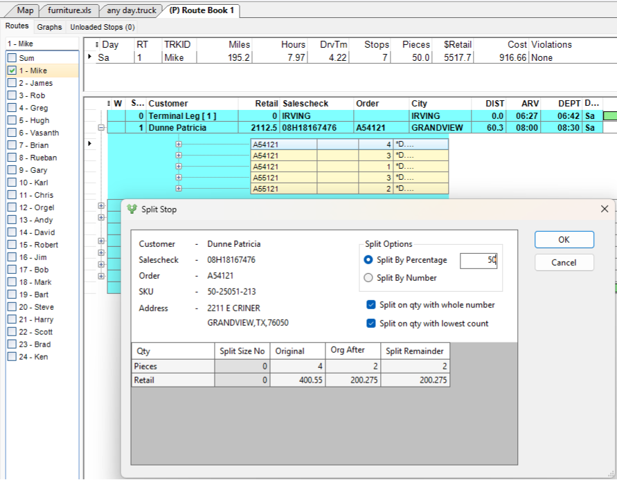 Figure 71. Manually split a Route by percentage
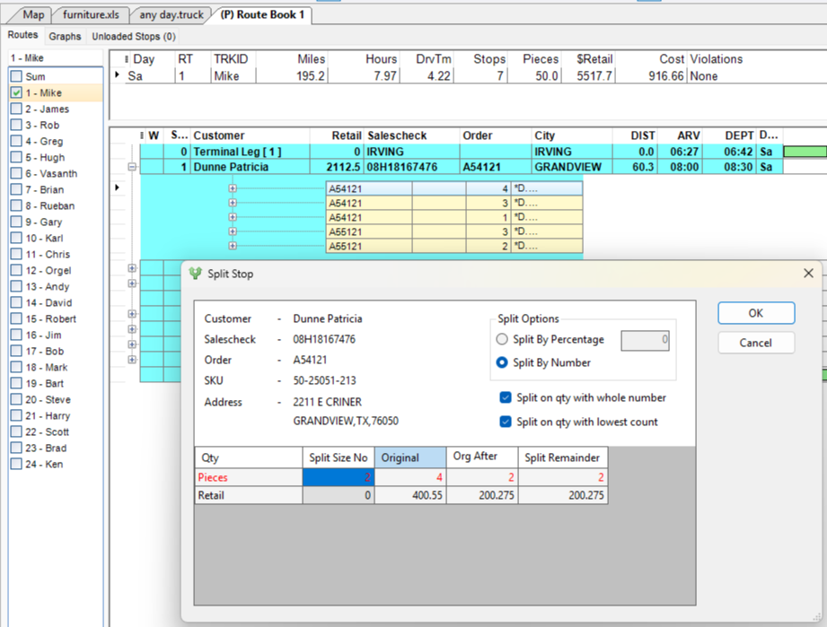 Figure 72. Manually split a Route by number (quantity)
Time & Speed-based Adjustments
DirectRoute provides a wide range of optional speed and time settings that help build Routes that consider many real-world factors drivers might encounter.
There are two types of Speed adjustments — Project level and Stop/Truck file-based, and three time-related adjustments to choose from.
SPEED ADJUSTMENTS
- Project-level Speed Adjustments
-
If one chooses not to use a Distance file, they can set a speed and speed adjustment in their Routing Preferences for the algorithm to use with every routing solution. See Routing> General> Speed to enable this functionality.
The Speed field indicates the average speed for all vehicles included in the routing solution (e.g., 60).
-
A Speed entry of 0 means the user is opting for the proprietary Route speed calculation rather than a user-defined value.
The Speed Adjustment is the percentage increase or decrease on top of the average speed entered.
-
A speed adjustment entry of 100% means no adjustments are made.
For example, a Speed adjustment of 120% decreases the speed of the Route because it increases the time by 20%. An 80% adjustment increases the speed because it decreases the time by 20%. (.5 hrs x .80 = .4 30 mins x .80 = 24 mins — The Route went from 30 mins to 24 mins)
-
- Stop & Truck File-Based Adjustments
-
In addition to project-level speed settings, adjustments can be defined to accommodate known occurrences such as rush hour traffic slow-downs or construction season (zones) in Route calculations using optional fields in the Stop and Truck files.
The speed adjustment is applied at a given time or location, and the adjustment period ends after the indicated period expires. For instance, a Zone Speed Adjustment works anytime a vehicle enters the specified zone and remains in that adjusted period for 8 miles. See the table below.
-
Project-level and Stop/ Truck file speed adjustments are compounded when used together.
-
File |
Field |
Distance (Radius) |
Center of Radius |
Stop |
Zone |
8 miles, 24 hours a day |
Next stop in sequence |
Truck |
Zone |
8 miles, 24 hours a day |
Depot |
File |
Fields |
Distance (Radius) |
Center of Radius |
Stop |
AMAdj, PMAdj %Adj |
The Rush Hour Distance set in Preferences |
Next stop in sequence |
Truck |
AMAdj, PMAdj %Adj |
The Rush Hour Distance set in Preferences |
Depot |
TIME ADJUSTMENTS
There are three different settings to account for time and time adjustments. Use these quick links or scroll below.
- TIME BETWEEN STOPS
-
Include a mandatory time block between each Stop during the route-building process. When enabled, this option tells DirectRoute to apply the designated time, eliminating the need to add time to Stops, and create accurately planned arrival times. To use this capability, two settings are used in Preferences under Routing > General.
-
Apply Min Time Between Stops After Directions — This field must be set to TRUE.
-
Minimum Time Between Stops — The number of minutes DirectRoute applies between Stops.
-
Option can be used with any existing Route file or applied when creating new Routes.
-
For existing Routes — DirectRoute recalculates the estimated arrival times for affected Stops and updates the Route Book accordingly.
-
-
If the option is set, but not required for each Route, the option can be turned on and off within the Route Book. See the DirectRoute User Guide.
-
- TIME WINDOWS
-
Time Windows allow Stops to deliver or unload before or after the actual delivery window (known as an early or late buffer) in exchange for a penalty cost. Only use with customers that allow an early or late delivery.
-
Penalties are applied each time a delivery occurs outside the time window.
-
Time Windows, Buffers, and Penalty Costs are set in Preferences under Defaults.
-
Reversing Time Windows may cause Window Violations or a failure to load Stops.
EXAMPLE
-
Early/ Late Buffers — 1 hour
-
Penalty Cost — $20/hr.
-
Time Windows — Open1/Close1 = 0700-1000; Open2/Close2 = 1300-1700
-
The truck arrives at the Stop at 0645. It is considered early, but within the one-hour buffer period, so no Window Violation is generated
-
A penalty is assessed against the Stop — 15 min (.25) x $20 = $5
-
- TIME WINDOW GAP BUFFER
-
Time Window Gap Buffer is used to determine if the Early/ Late buffers for the Time Windows should be used or ignored. The Gap Buffer default is 1.75hrs. See the examples below for clarity.
EXAMPLE 1
-
Gap Buffer — 1.75 hrs. (default)
-
Early/Late Buffers — .5 (30 mins)
-
Time Windows — Open1/Close1 = 0700-1100; Open2/Close2 = 1300-1700
-
There is a two-hour gap between the first window set and the second window set (1100-1300)
-
Because the Gap Buffer is less than the timeframe between the Time Windows, the Gap Buffer is ignored, and the Time Windows option is used
EXAMPLE 2
-
Gap Buffer — 1.75 hrs. (default)
-
Early/Late Buffers — .5 (30 mins)
-
Time Windows — Open1/ Close1 = 0700-1230; Open2/Close2 = 1330-1700
-
There is a one-hour gap between the first window set and the second window set (1230-1330)
-
Because the Gap Buffer is greater than the 1-Hr gap between the two window sets, the Gap Buffer is used. The Early/Late Buffers are ignored
EXAMPLE 3
-
Gap Buffer — 1.75 hrs. (default)
-
Delivery time — 2100 until 0300
-
Time Windows — Open1/Close1 = 0-0300; Open2/Close2 = 2100-2400
-
The earliest period (midnight to morning) must be placed first.
-
Ensure the midnight Time Window is covered on the proper day
-
-
Because the Gap Buffer is less than the timeframe between the Time Windows, the Gap Buffer is ignored, and the Time Windows option is used
Turn-by-turn Directions
Turn-by-turn directions can be created after the Route is built. The directions are acquired through DirectRoute’s mileage system that adheres to all routing preferences selected for the routing solution (e.g., time windows, speed adjustments). PC*Miler is for its licensed users; Trimble MAPS mileage system is for all other users.
-
When the Route is saved, the directions are saved in the Route file.
-
Optimize/ Modify Routes prior to generating directions. The optimization process overwrites the original and new directions need to be regenerated.
-
Use the Generate Route Directs on Route Edit from the main menu to update the directions after edits have been made.
-
The Generating Route Directions info box appears in the lower left corner indicating new directions are being generated.
-
-
When directions are generated, Route lines, on the map, follow the road network to connect the Stops (opposed to straight lines / crow flies).
ROUTE DIRECTIONS WINDOW
This window displays three tabs containing different variables for maximum control. The General tab appears for all users. The other two tabs — Trimble Maps and PCMiler Direct — appear based on the mileage system chosen. Explore the tabs and variables below.
- GENERAL TAB
-
-
From Route / To Route — Identifies the Routes that require directions (e.g., Enter 1 and 5 to generate directions for Routes between 1 - 5 only).
-
Use DirectRoute Drive Time — When selected, DirectRoute generates drive times using proprietary calculations based on time and distance data obtained from PCMiler (only replaces PCMiler generated drive times).
-
If this option is not selected, DirectRoute may not adhere to the default values and rules that are selected to build the Routes. May cause a change in drive times, distances between Stops, minimum times between Stops, etc.
-
-
Use Mileage System Drv Tm if greater than DirectRoute Drv Tm — Use with DirectRoute Drive Time setting. When selected, it ensures the slower drive time is selected when the PC*Miler drive time is greater than what is calculated by DirectRoute.
-
Update Distance File — Adds distance entries for any Stops that do not already have entries in the Distance file.
-
Overwrite Existing Distance Entries — Will overwrite the current Distance File entries, if different from those currently posted in the Distance File.
-
Optimize Sequence — Optimizes the Stops sequence for each Route based on the distance between Stops.
-
May rearrange Stops to occur in order of their location (map point sequence) regardless of time windows.
-
May cause sequence violations.
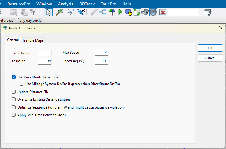 Figure 73. Route Directions General Tab
-
-
TRIMBLE MAPS vs PC*MILER MILEAGE SYSTEMS
-
Trimble Maps (default) enables the use of APIs that access actively updated information.
-
PCM*Direct disables all API calls, and PC*Miler is used for all mileage and transit calculations.
View other differences using the table below:
Trimble Maps |
PC*Miler |
Vehicle Profile — Select from the drop-down menu (most data auto-populates when the profile is selected) Elevation — Elevation limit, if applicable, in Feet/ Meters. Should match unit chosen in Distance Options preference
Route Type
Hazardous Materials — Select the option that applies Toll Usage
Use Toll Discounts — Enables the use of multi-state toll discount programs. Route Across National Borders — Enables DirectRoute to build a Route where one or more trucks may cross a US National border in pursuit of a customer delivery. Use Historical Traffic Data — Historical traffic patterns are used rather than real-time traffic data Use Content Tools — Highway Only — Local streets are not considered when building the Route. Vehicles are restricted to primary roads and/or Highways regardless of vehicle profile. PCM Version — Related to the user’s Map API key configuration and licensing in the Admin Portal. (Find your API key in the About DirectRoute window and Licenses tab).
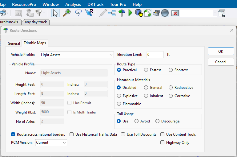
Figure 74. Trimble Maps Tab (click on image to enlarge)
|
Vehicle Profile — Select from the drop-down menu (most data auto-populates when the profile is selected)
Hazardous Materials — Select the option that applies Toll Usage
Route Across National Borders — Enables DirectRoute to build a Route where one or more trucks may cross a US National border in pursuit of a customer delivery. Use Historical Traffic Data — Historical traffic patterns are used rather than real-time traffic data 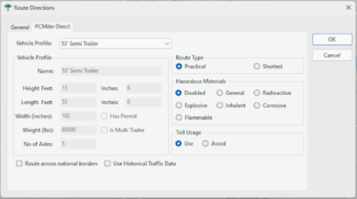
Figure 75. PC*Miler Mileage System (click on image to enlarge)
|
Ultrafast Distance Matrix
UltraFast Distance Matrix (UFDM) allows users to generate distances and drive times, in near real-time, between millions of locations.
Users must create a Distance file using the Ultrafast Distance Matrix. Internet connection required.
-
There can be up to a 5% discrepancy from actual distance when using the UFDM.
-
Does not support time-based restrictions or Ferry links.
-
Can only be used when leveraging Preprocessing while in route-building mode using either DirectRoute or TransportationModeler.
-
Preference changes must be defined and options enabled prior to creating routes. Set these values under Preferences > Preprocess > Generate Distance File.
-
Generate Distance File — Must select Ultrafast.
-
Use DirectRoute Drive Time — Set to False to enable UFDM.
-
To enable, see the section on UFDM in the DirectRoute User Guide.
Modifications & Optimizations
The application offers several ways to both customize and optimize the way a Route is built and refined to lower operating costs, maximize a fleet, and improve Route performance.
Route Modifications
Modifications are completed when small adjustments are needed after the Route build. They can be achieved in many ways within DirectRoute. The following are the two most popular ways:
-
Use the Modify menu when the Route file is open. These actions are described below.
-
Right-click on a Route found in the Route tab of the Route Book.
Although some Route modifications appear in both locations, the menus are not identical. See the Route Book section for a description of those modification options.
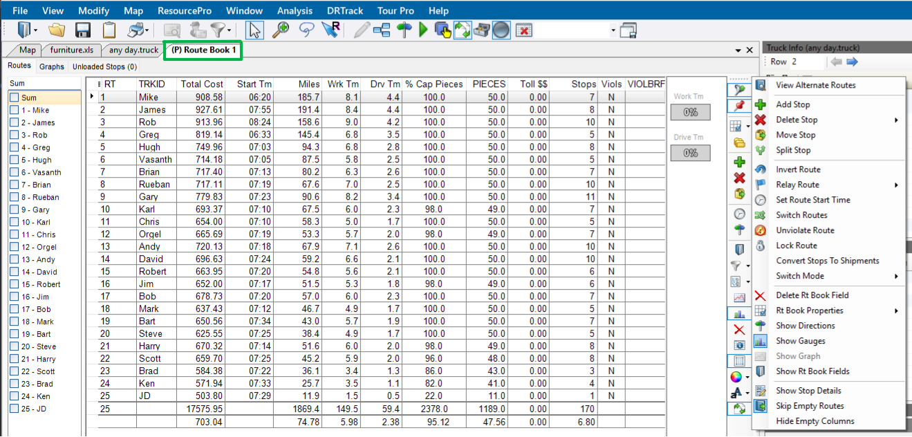
MODIFY MENU:
-
Undo / Redo — Easy way to undo or redo an action just performed on a Route.
-
Add Stop — Add a Stop, to a specific position, on a Route (Can also be done from the Map).
-
Delete Stop — Delete a single Stop, a range of Stops, or delete all Stops from one or multiple Routes.
-
Move Stop — Move a single Stop or a range of Stops from one Route to another.
-
Load unloaded Stops — Allows DirectRoute to determine the best location to place Unloaded Stops.
-
Stops may not load because it violates a restriction to Time windows, Work time, Drive time, Capacity constraints, or EQCodes. Review the Stops in the Route Book’s Unload Stops tab to determine why they were not loaded in the original build before manually loading to a Route.
-
-
Reload Stops — Allows DirectRoute to take Stops from an existing Route and determine the next best Route.
-
Allow Rejection — Check the box to provide a warning for the cost of the move to allow acceptance or decline before committing to the move.
-
Allow load on empty Route — Check the box to allow a reloaded Stop to be placed on an empty Route.
-
Allow load on displayed Routes only — Check the box to allow a Stop to be reloaded only on Routes that are displayed on the screen. All other Routes are ignored during the reload sequence.
-
-
Edit Leg — Enables the deletion or insertion of another leg anywhere in a Route.
-
Invert Route — Reverses the sequence of Stops on a Route.
-
Lock Routes — Limits the amount of alterations the optimization actions can have on a Route. Users can lock a single Route or multiple Routes at one time. Check out this Locking Routes video for more info.
-
No lock — Routes can be added to, deleted from, or re-sequenced. No limitations.
-
Prevent Removal — No Stop can be removed from the Route; only re-sequencing or adding Stops may take place.
-
Prevent Addition — Stop may be removed and re-sequenced, but new Stops cannot be added.
-
Prevent Removal and Addition — Stops can be re-sequenced only.
-
Prevent Any Changes — No changes can be made on the Route.
-
-
Set Route Start Time — Adjustment the start time for one or multiple Routes.
-
Switch Routes — Switch Trucks between Routes.
-
Unviolate Routes — Remove violation flags from Stops on a Route. E.g., A Stop violates a time window, but the user decides to deliver the Stop anyway. The command removes the flag, but it can change other settings.
-
Change Stop Sequence — Change the sequence of Stops on a Route.
Route Optimizations
When optimizing, DirectRoute performs additional passes over the routing data to look for options that allow Stops to be moved within or between Routes to return a lower-cost routing solution. Additional options can be selected to encourage loading the unloaded Stops at the same time.
-
Choose the Optimization settings before the Route building process begins or apply preferences to Routes already built.
-
All necessary cost fields within the Truck file must be accurate for the optimization process to be effective.
-
Set the mileage cost, fixed cost, and hourly cost for each type. The larger the truck, the higher the value.
-
Set a higher value for vehicle that should be used only as a last resort, to a higher value.
-
Use these quick links to review the optimization options or scroll below:
OPTIMIZATION OPTIONS:
- Optimize Trucks After Loading
-
Automatically engages Truck Optimization.
-
DirectRoute chooses the right vehicle for each Route when there is a mixed fleet (different types/sizes).
-
Goal is to minimize costs by moving Stops from larger, underutilized, expensive trucks to cheaper, smaller trucks using the costs found in the Truck file.
-
Use Optimize Trucks After Loading when:
-
There is a mix of vehicle types in the Truck file.
-
Some vehicles should only be used as a last resort (rentals).
-
Some Stops did not load because there were no available vehicles.
-
-
- Optimize Stops After Loading
-
Automatically engages Between Route Optimization. Aims to minimize costs by moving Stops between and within Routes. Preferences include:
-
From RT — The first Route to be optimized. (E.g., If the From RT is set to 6, the Optimization process starts at Route number 6).
-
To RT — Last Route to be optimized creating a range with the From RT value. Only Stops within this range are considered for optimization.
-
Level — The number of Stops reviewed at one time to determine if they can be moved to another position or Route (4 is the recommended).
-
Cutoff Amt — Minimum cost savings incurred to evaluate moving a Stop or leaving it in its current order. (e.g., If 5 is entered, DirectRoute does not change a Route unless at least $5 will be saved by moving the Stop).
-
Time Limit — Max amount of time the optimization routines can run.
-
DirectRoute reviews the highest marginal cost Stops first, so most cost savings occur early in the optimization process, and the process generally does not max out the time.
-
-
Penalty Amount — An arbitrary dollar amount applied to Stops that are moved within a Route. This dollar amount does not affect the cost of the Route but counts as a penalty against the move.
-
Penalty Factor — Multiplier for the individual penalties displayed on the Penalty tab.
-
The Penalty tab provides control over the individual penalties applied when occurrences of these violations are counted.
-
The Optimization algorithm adds to the Route cost using the following formula: Total Penalty Cost = # of Violations * Penalty Factor * Cost Per Stop * Violation Penalty Weight.
-
-
- Optimize Within Routes
-
Manually engage a Route modification. Attempts to re-order the Stops within a Route to lower the overall cost.
- Optimize Between Routes
-
Manually engage a Route modification. Evaluates the effects of moving one or more Stop(s) to other Routes to lower the overall cost. Preferences include:
-
Level — Number of Stops reviewed at one time to determine if they can be moved to another position or another Route.
-
Number is 50% of the average Stops per Route in each specific project.
-
Default is 4. I.e., 8 Stops per Route is the average between all customers and projects within DirectRoute to date.
-
The higher the level, the longer it takes to process.
-
A lower level setting may result in fewer cost savings.
Example
There are two Routes. Level is set to 4, so it evaluates moving a cluster of 4 Stops to another Route.
DirectRoute evaluates Stops #1, #2, and #3 on Route #1 to determine if there is a cost savings in moving them to Route #2.
A lower level would not evaluate enough Stops to make a real cost savings given that Stops #1 — #3 are all in the same location.
-
-
Pass Limit — Limits the number of times a Route passes through the optimization process.
-
Default is 2.
-
Two passes find up to 95% of the potential savings.
-
Three or more passes are required to find maximum savings in a project.
-
-
Cutoff Amount — Minimum cost savings incurred to evaluate moving a Stop or leaving it in its current order (e.g., If 5 is entered, DirectRoute does not change a Route unless at least $5 will be saved by moving the Stop).
-
Max Time — Max amount of time the optimization routines can run.
-
DirectRoute reviews the highest marginal cost Stops first, so most cost savings occur early in the optimization process, and the process generally does not max out the time.
-
-
1st Pass and Subsequent Passes — Designates the amount of time each pass can spend evaluating moves or swaps.
-
These times are combined to make up the total allowed time for optimization.
-
If the combined time is less than the Max Time, optimization halts when the pass settings are met.
-
Move Time — Designates the amount of time DirectRoute spends evaluating moves within the first pass (in minutes).
-
Moves are defined as Stops changing from one Route to another; Not a Stop sequence change.
-
-
Swap Time — Designates the amount of time DirectRoute spends evaluating swaps between Routes within the first pass (in minutes).
-
Swaps are defined as an equal number of Stops exchanged between two Routes.
-
-
-
Attempt loading unloaded — When this box is checked, DirectRoute attempts to load any Stops that appear on the Unloaded Stop page in the Route Book.
-
Optimize displayed routes — When this box is checked, DirectRoute only optimizes Routes that are locked on the screen. All other Routes are ignored.
-
Penalty Factor — Multiplier for the individual penalties displayed on the Penalty tab.
-
The Penalty tab provides control over the individual penalties applied when occurrences of these violations are counted.
-
The Optimization algorithm adds to the Route cost using the following formula: Total Penalty Cost = # of Violations * Penalty Factor * Cost Per Stop * Violation Penalty Weight.
Individual penalties that can be applied are:
-
Start Costing — Modifies the start time of a Route.
Total Penalty Cost = Arrival Time - Open Time * Penalty Factor * TruckHourCost * Start Costing Penalty Weight.
-
Time Window (TW) — Modifies Routes with a Time Window violation.
Total Penalty Cost = # of TW Violations * Penalty Factor * Cost Per Stop * TW Penalty Weight.
-
Eq Code Modifies Routes with an EqCode violation.
Total Penalty Cost = # of EqCode Violations * Penalty Factor * Cost Per Stop * EqCode Penalty Weight.
-
Work Time (WT) — Modifies Routes with a Work Time violation.
Total Penalty Cost = # of WT Violations * Penalty Factor * Cost Per Stop * WT Penalty Weight.
-
Capacity (Cap) — Modifies Routes with a Capacity violation.
Total Penalty Cost = # of Cap Violations * Penalty Factor * Cost Per Stop * Capacity Penalty Weight.
-
-
-
Add-ons and Modules
There are a number of Appian add-ons or modules customers can purchase to enhance the functionality of DirectRoute.
Click to view
Some modules can be used as a stand-alone application, others act as DirectRoute add-ons. Review the options below for details.
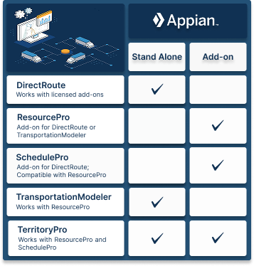
RESOURCEPRO
ResourcePro (RP) is a DirectRoute or TransportationModeler optimization tool add-on that considers drivers and power units required for weekly schedules to reduce driver hours and under-utilized equipment, minimizing the fleet size needed to operate a dedicated business.
Learn more: ResourcePro User Guide
SCHEDULEPRO
SchedulePro (SP) is a DirectRoute fleet scheduling tool add-on used to optimize a planned route based on the customer’s volume and delivery patterns across a 1-12 week planning period.
Learn more: SchedulePro User Guide
TERRITORYPRO
TerritoryPro (TP) is an automated territory building software used to create and adjust territories based on a host of shipping constraints e.g., sales volumes and coverage area. Use as a stand-alone product or DirectRoute add-on (also works with SchedulePro or ResourcePro).
Learn more: TerritoryPro User Guide
TRANSPORTATIONMODELER
TransportationModeler ™ is a shipper and carrier tool used to solve transportation problems that occur when deliveries have both an origin and destination not associated with the driver/ Truck terminal and mixed fleets, backhauls, or Less-than-Load (LTL) shipments.
Learn more: TransportationModeler User Guide
Integrations
DirectRoute can integrate with many third parties as well as other Trimble applications to provide a seamless user experience.
Click to view
Integrate DirectRoute with many ERP, WMS, and Order Management Systems with the use of .CSV, .TXT, and .XLS files. Check out this Appian Integration Options video for more info.
In addition to the add-ons and modules described in the section above, DirectRoute can integrate with the following Trimble applications.
TMWSuite
TMWSuite is a Windows-based, client-server, software application for use by truckload motor carriers and logistics firms to help manage dispatch, billing, and settlement functions. The TMWSuite DirectRoute integration allows users to send orders from TMWSuite to Appian DirectRoute for Route planning optimization. DirectRoute consolidates the orders into one or more movements and determines the best Route for the trip.
For further details, see the TMWSuite DirectRoute Integration doc.
TruckMate
The TruckMate integration with DirectRoute allows its users the benefits of DirectRoute from within the TruckMate application. When there is a need to optimize a Route, the freight bills are sent from TruckMate to DirectRoute, DirectRoute’s algorithm does its magic, and the results are returned to TruckMate. TruckMate then translates the results into trips and trip Routes. There is no additional TruckMate license to run the DirectRoute integration; however, users must have DirectRoute installed to integrate.
For more information, visit the Appian DirectRoute Integration doc.
Resources
Related Documents
Support
Email: [email protected]
US (toll-free): 1-800-663-0626
Monday-Friday, 7am-5pm CST